DA14580
FINAL
Bluetooth Low Energy 4.2 SoC
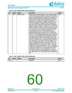
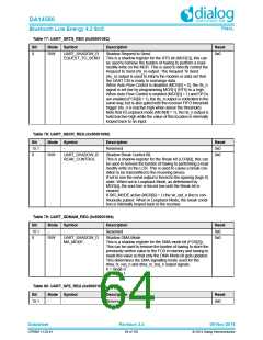
Table 77: UART_SRTS_REG (0x5000108C)
Bit
Mode Symbol
R/W UART_SHADOW_R
EQUEST_TO_SEND
Description
Reset
0
Shadow Request to Send.
0x0
This is a shadow register for the RTS bit (MCR[1]), this can
be used to remove the burden of having to perform a read-
modify-write on the MCR. This is used to directly control the
Request to Send (rts_n) output. The Request To Send
(rts_n) output is used to inform the modem or data set that
the UART Ctrl is ready to exchange data.
When Auto Flow Control is disabled (MCR[5] = 0), the rts_n
signal is set low by programming MCR[1] (RTS) to a high.
When Auto Flow Control is enabled (MCR[5] = 1) and FIFOs
are enabled (FCR[0] = 1), the rts_n output is controlled in the
same way, but is also gated with the receiver FIFO threshold
trigger (rts_n is inactive high when above the threshold).
Note that in Loopback mode (MCR[4] = 1), the rts_n output is
held inactive-high while the value of this location is internally
looped back to an input.
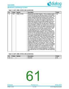
Table 78: UART_SBCR_REG (0x50001090)
Bit
15:1
0
Mode Symbol
Description
Reset
0x0
-
-
Reserved
R/W
UART_SHADOW_B
REAK_CONTROL
Shadow Break Control Bit.
0x0
This is a shadow register for the Break bit (LCR[6]), this can
be used to remove the burden of having to performing a read
modify write on the LCR. This is used to cause a break con-
dition to be transmitted to the receiving device.
If set to one the serial output is forced to the spacing (logic 0)
state. When not in Loopback Mode, as determined by
MCR[4], the sout line is forced low until the Break bit is
cleared.
If SIR_MODE active (MCR[6] = 1) the sir_out_n line is con-
tinuously pulsed. When in Loopback Mode, the break condi-
tion is internally looped back to the receiver.
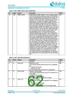
Table 79: UART_SDMAM_REG (0x50001094)
Bit
15:1
0
Mode Symbol
Description
Reset
0x0
-
-
Reserved
R/W
UART_SHADOW_D
MA_MODE
Shadow DMA Mode.
0x0
This is a shadow register for the DMA mode bit (FCR[3]).
This can be used to remove the burden of having to store the
previously written value to the FCR in memory and having to
mask this value so that only the DMA Mode bit gets updated.
This determines the DMA signalling mode used for the
dma_tx_req_n and dma_rx_req_n output signals.
0 = mode 0
1 = mode 1
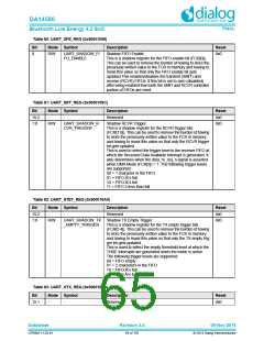
Table 80: UART_SFE_REG (0x50001098)
Bit
Mode Symbol
Description
Reset
15:1
-
-
Reserved
0x0
Datasheet
Revision 3.4
09-Nov-2016
CFR0011-120-01
64 of 155
© 2014 Dialog Semiconductor

 DIALOG [ Dialog Semiconductor ]