HBR Series of Railway Half-Brick
[Type text]
[Type text]
[Type text]
Up to 150 Watts DC-DC Converter
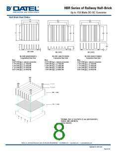
is approved. Low resistance and low inductance PCB layout should be
used where possible. Proper attention must also be given to low
impedance tracks between power module, input and output grounds.
The recommended footprints and soldering profiles are shown in the
next two figures.
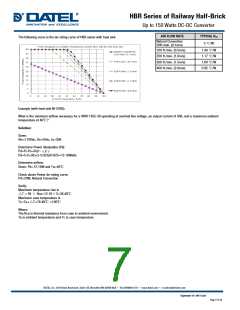
Operating Temperature Range
This HBR series of converters is rated to operate over a wide case
temperature range of -40°C to +100°C. Consideration must be given
to the de-rating curves when ascertaining maximum power that can
be drawn from the converter. The maximum power drawn from half
brick models is influenced by usual factors, such as:
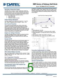
Lead Free Wave Soldering Profile
•
•
•
Input voltage range
Output load current
Forced air or natural convection
300
250
200
150
100
50
Output Voltage Adjustment
The output voltage for the on HBR series outputs of 5, 12 and 24
Volts models is adjustable within the range of +10% to –10%.
Over Current Protection
0
The converter is protected against over current or short circuit
conditions. At the instance of current-limit inception, the module
enters a hiccup mode of operation, whereby it shuts down and
automatically attempts to restart. While the fault condition exists, the
module will remain in this hiccup mode, and can remain in this mode
until the fault is cleared. The unit operates normally once the output
current is reduced back into its specified range.
0
50
100
150
Time (Seconds)
Note:
1. Soldering Materials: Sn/Cu/Ni
2. Ramp up rate during preheat: 1.4 ℃/Sec (From 50℃ to 100℃)
3. Soaking temperature: 0.5 ℃/Sec (From 100℃ to 130℃), 60 20
seconds
Output over Voltage Protection
The output overvoltage protection consists of an internal circuit that
limits the output voltage. If more accurate output over voltage
protection is required, then an external circuit can be used via the
remote on/off pin.
4. Peak temperature: 260℃, above 250℃ 3~6 Seconds
5. Ramp rate during cooling: -10.0 ℃/Sec (From 260℃ to 150℃)
Remote On/Off
The On/Off input pin permits the user to turn the power module on or
off via a system signal. Two remote on/off options are available.
Positive logic turns the module on during a logic high voltage on the
On/Off pin, and off during a logic low. The On/Off pin is internally
pulled up through a resistor. A properly de-bounced mechanical
switch, open collector transistor, or FET can be used to drive the input
of the On/Off pin. If not using the remote on/off feature, leave the
On/Off pin open. Models with part number suffix “N” are the “negative
logic” remote on/off version. The unit turns off if the remote on/off pin
is high (>3.5Vdc or open circuit). The converter turns on if the on/off
pin input is low (<1.8Vdc). Note that the converter is off by default.
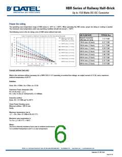
Convection Requirements for Cooling
To predict the approximate cooling needed for the half brick module,
refer to the power de-rating curves in the next section These de-rating
curves are approximations of the ambient temperatures and airflows
required to keep the power module temperature below its maximum
rating. Once the module is assembled in the actual system, the
module’s temperature should be monitored to ensure it does not
exceed 100°C as being measured at the center of the top of the case
(thus verifying proper cooling).
UVLO (Under Voltage Lock Out)
Input under voltage lockout is standard with this converter. At input
voltages below the input under voltage lockout limit, the module
operation is disabled.
Over Temperature Protection
These modules have an over temperature protection circuit to
safeguard against thermal damage.
When the case temperature rises above over temperature shutdown
threshold, the converter will shut down to protect it from overheating.
The module will automatically restart after it cools down.
Thermal Considerations
The power module operates in a variety of thermal environments;
however, sufficient cooling should be provided to help ensure reliable
operation of the unit. Heat is removed by conduction, convection, and
radiation to the surrounding environment. The test data is presented
in the next section. The power output of the module should not be
allowed to exceed rated power (Vo_set x Io_max).
Recommended Layout, PCB Footprint and
Soldering Information
The user must ensure that other components and metal in the vicinity
of the converter meet the spacing requirements to which the system
September 16 -2017 A.04
Page 5 of 15

 DATEL [ DATEL, Inc. ]