HBR Series of Railway Half-Brick
[Type text]
[Type text]
[Type text]
Up to 150 Watts DC-DC Converter
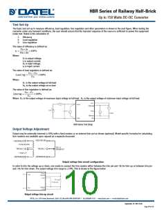
Test Set-Up
The basic test set-up to measure efficiency, load regulation, line regulation and other parameters is shown in the next figure. When testing the
converter under any transient conditions, the user should ensure that the transient response of the source is sufficient to power the equipment
under test. Below is the calculation of:
1- Efficiency
2- Load regulation
3- Line regulation
The value of efficiency is defined as:
Vo× Io
Vin× Iin
η =
×100%
Where:
Vo is output voltage,
Io is output current,
Vin is input voltage,
Iin is input current.
The value of load regulation is defined as:
FL −V
NL ×100%
NL
V
Load.reg =
V
Where:
V
FL is the output voltage at full load
VNL is the output voltage at no load
The value of line regulation is defined as:
HL −V
LL ×100%
LL
V
Line.reg =
V
Where: VHL is the output voltage of maximum input voltage at full load. VLL is the output voltage of minimum input voltage at full load.
HBR Series Test Setup
Output Voltage Adjustment
Output may be externally trimmed ( 10%) with a fixed resistor or an external trim-pot as shown (optional). Model specific formulas for calculating
trim resistors are available upon request as a separate document
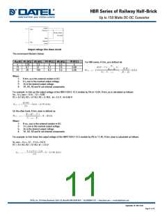
Output voltage trim circuit configuration
In order to trim the voltage up or down, one needs to connect the trim resistor either between the trim pin and -Vo for trim-up or between trim pin
and +Vo for trim-down. The output voltage trim range is 10%. This is shown in the figure below
Output voltage trim up circuit
September 16 -2017 A.04
Page 10 of 15

 DATEL [ DATEL, Inc. ]