3D7225
SILICON DELAY LINE AUTOMATED TESTING
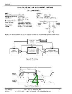
TEST CONDITIONS
INPUT:
OUTPUT:
Ambient Temperature: 25oC ± 3oC
Supply Voltage (Vcc): 5.0V ± 0.1V
Rload
Cload
:
:
10KΩ ± 10%
5pf ± 10%
Input Pulse:
High = 3.0V ± 0.1V
Threshold: 1.5V (Rising & Falling)
Low = 0.0V ± 0.1V
50Ω Max.
Source Impedance:
Rise/Fall Time:
3.0 ns Max. (measured
between 0.6V and 2.4V )
PWIN = 1.25 x Total Delay
PERIN = 2.5 x Total Delay
Device
Digital
Scope
10KΩ
Under
Test
Pulse Width:
Period:
5pf
470Ω
NOTE: The above conditions are for test only and do not in any way restrict the operation of the device.
PRINTER
COMPUTER
SYSTEM
OUT1
REF
OUT2
OUT3
OUT4
OUT5
DEVICE UNDER
TEST (DUT)
PULSE
OUT
IN
DIGITAL SCOPE/
GENERATOR
TIME INTERVAL COUNTER
TRIG
IN
TRIG
Figure 2: Test Setup
PERIN
PWIN
tRISE
tFALL
INPUT
VIH
2.4V
1.5V
2.4V
1.5V
0.6V
SIGNAL
VIL
0.6V
tPLH
tPHL
OUTPUT
SIGNAL
VOH
1.5V
1.5V
VOL
Figure 3: Timing Diagram
Doc #05002
4/15/05
DATA DELAY DEVICES, INC.
Tel: 973-773-2299 Fax: 973-773-9672 http://www.datadelay.com
4

 DATADELAY [ DATA DELAY DEVICES, INC. ]