3D7010
SILICON DELAY LINE AUTOMATED TESTING
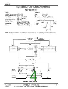
TEST CONDITIONS
INPUT:
OUTPUT:
Ambient Temperature: 25oC ± 3oC
Supply Voltage (Vcc): 5.0V ± 0.1V
Rload
Cload
:
:
10KΩ ± 10%
5pf ± 10%
Input Pulse:
High = 3.0V ± 0.1V
Threshold: 1.5V (Rising & Falling)
Low = 0.0V ± 0.1V
50Ω Max.
Source Impedance:
Rise/Fall Time:
3.0 ns Max. (measured
between 0.6V and 2.4V )
PWIN = 1.25 x Total Delay
PERIN = 2.5 x Total Delay
Device
Digital
Scope
10KΩ
Under
Test
Pulse Width:
Period:
5pf
470Ω
NOTE: The above conditions are for test only and do not in any way restrict the operation of the device.
PRINTER
COMPUTER
SYSTEM
OUT1
REF
OUT2
PULSE
OUT
IN
DIGITAL SCOPE/
DEVICE UNDER
TEST (DUT)
OUT3
OUT4
OUT5
OUT6
OUT7
OUT8
OUT9
OUT10
GENERATOR
TIME INTERVAL COUNTER
TRIG
IN
TRIG
Figure 2: Test Setup
PERIN
PWIN
tRISE
tFALL
INPUT
VIH
2.4V
1.5V
2.4V
1.5V
0.6V
SIGNAL
VIL
0.6V
tPLH
tPHL
OUTPUT
SIGNAL
VOH
1.5V
1.5V
VOL
Figure 3: Timing Diagram
Doc #96004
12/2/96
DATA DELAY DEVICES, INC.
Tel: 973-773-2299 Fax: 973-773-9672 http://www.datadelay.com
4

 DATADELAY [ DATA DELAY DEVICES, INC. ]