3D7010
APPLICATION NOTES
To guarantee the Table 1 delay accuracy for
input frequencies higher than the Maximum
Operating Frequency, the 3D7010 must be
tested at the user operating frequency.
OPERATIONAL DESCRIPTION
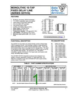
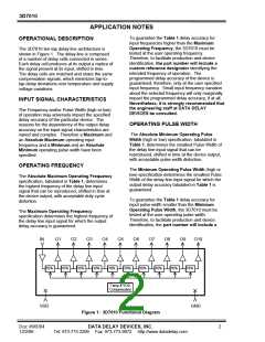
The 3D7010 ten-tap delay line architecture is
shown in Figure 1. The delay line is composed
of a number of delay cells connected in series.
Each delay cell produces at its output a replica of
the signal present at its input, shifted in time.
The delay cells are matched and share the same
compensation signals, which minimizes tap-to-
tap delay deviations over temperature and supply
voltage variations.
Therefore, to facilitate production and device
identification, the part number will include a
custom reference designator identifying the
intended frequency of operation. The
programmed delay accuracy of the device is
guaranteed, therefore, only at the user specified
input frequency. Small input frequency variation
about the selected frequency will only marginally
impact the programmed delay accuracy, if at all.
Nevertheless, it is strongly recommended that
the engineering staff at DATA DELAY
DEVICES be consulted.
INPUT SIGNAL CHARACTERISTICS
The Frequency and/or Pulse Width (high or low)
of operation may adversely impact the specified
delay accuracy of the particular device. The
reasons for the dependency of the output delay
accuracy on the input signal characteristics are
varied and complex. Therefore a Maximum and
an Absolute Maximum operating input
frequency and a Minimum and an Absolute
Minimum operating pulse width have been
specified.
OPERATING PULSE WIDTH
The Absolute Minimum Operating Pulse
Width (high or low) specification, tabulated in
Table 1, determines the smallest Pulse Width of
the delay line input signal that can be
reproduced, shifted in time at the device output,
with acceptable pulse width distortion.
OPERATING FREQUENCY
The Minimum Operating Pulse Width (high or
low) specification determines the smallest Pulse
Width of the delay line input signal for which the
output delay accuracy tabulated in Table 1 is
guaranteed.
The Absolute Maximum Operating Frequency
specification, tabulated in Table 1, determines
the highest frequency of the delay line input
signal that can be reproduced, shifted in time at
the device output, with acceptable duty cycle
distortion.
To guarantee the Table 1 delay accuracy for
input pulse width smaller than the Minimum
Operating Pulse Width, the 3D7010 must be
tested at the user operating pulse width.
The Maximum Operating Frequency
specification determines the highest frequency of
the delay line input signal for which the output
delay accuracy is guaranteed.
Therefore, to facilitate production and device
identification, the part number will include a
IN
O1
O2
O3
O4
O5
O6
O7
O8
O9
O10
10%
10%
10%
10%
10%
10%
10%
10%
10%
10%
Temp & VDD
Compensation
VDD
GND
Figure 1: 3D7010 Functional Diagram
DATA DELAY DEVICES, INC.
Doc #96004
12/2/96
2
Tel: 973-773-2299 Fax: 973-773-9672 http://www.datadelay.com

 DATADELAY [ DATA DELAY DEVICES, INC. ]