DS1085
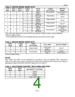
Table 2. DEVICE MODE USING OUT0
EN0
SEL0
(BIT)
PDN0
(BIT)
CTRL0
OUT0
(PIN)
CTRL0
DEVICE
(BIT)
(PIN)
FUNCTION
Power-Down*
MODE
Power-Down***
Active
1
0
1
0
1
0
1
0
1
0
1
0
High-Z
High-Z
MCLK/M
MCLK
High-Z
MCLK
High-Z
MCLK/M
High-Z
MCLK
High-Z
MCLK/M
0
0
1
0
1
0
1
0
0
0
0
1
1
Mux Select
Output Enable
Output Enable
Power-Down
Power-Down
0
Active
1
Active
1
Active**
Power-Down
Active
Power-Down
Active
X
X
*This mode is for applications where OUT0 is not used, but CTRL0 is used as a device shutdown.
**Factory default setting.
***See standby (power-down) current specification for power-down current range.
Table 3. DEVICE MODE USING OUT1
PDN1
CTRL1
CTRL1
OUT1 (PIN)
DEVICE MODE
(BIT)
(PIN)
FUNCTION
0
0
1
1
0
1
0
1
OUT CLK
High-Z
OUT CLK
High-Z
Output Enable
Active*
Active
Power-Down
Power-Down
*Factory default setting.
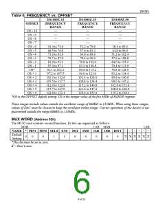
NOTE:
Both CTRL0 and CTRL1 can be configured as power-downs. They are internally “OR” connected so
either of the control pins can be used to provide a power-down function for the whole device, subject to
appropriate settings of the PDN0 and PDN1 register bits (see Table 4).
Table 4. SHUTDOWN CONTROL WITH PDN0 AND PDN1
PDN0
PDN1
SHUTDOWN CONTROL
(BIT)
(BIT)
0
0
1
1
0
1
0
1
NONE
CTRL1
CTRL0
CTRL1 OR CTRL0
4 of 21

 DALLAS [ DALLAS SEMICONDUCTOR ]