DS1085
2-WIRE SERIAL DATA BUS
The DS1085 communicates through a 2-wire serial interface. A device that sends data onto the bus is
defined as a transmitter, and a device receiving data as a receiver. The device that controls the message is
called a “master.” The devices that are controlled by the master are “slaves.” A master device that
generates the serial clock (SCL), controls the bus access, and generates the START and STOP conditions
must control the bus. The DS1085 operates as a slave on the 2-wire bus. Connections to the bus are made
through the open-drain I/O lines SDA and SCL.
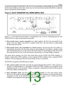
The following bus protocol has been defined (see Figure 2):
C Data transfer can be initiated only when the bus is not busy.
C During data transfer, the data line must remain stable whenever the clock line is HIGH. Changes in
the data line while the clock line is high are interpreted as control signals.
Accordingly, the following bus conditions have been defined:
Bus not busy: Both data and clock lines remain HIGH.
Start data transfer: A change in the state of the data line, from HIGH to LOW, while the clock is
HIGH, defines a START condition.
Stop data transfer: A change in the state of the data line, from LOW to HIGH, while the clock line is
HIGH, defines the STOP condition.
Data valid: The state of the data line represents valid data when, after a START condition, the data line
is stable for the duration of the HIGH period of the clock signal. The data on the line must be changed
during the LOW period of the clock signal. There is one clock pulse per bit of data.
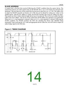
Each data transfer is initiated with a START condition and terminated with a STOP condition. The
number of data bytes transferred between START and STOP conditions is not limited, and is determined
by the master device. The information is transferred byte-wise and each receiver acknowledges with a
ninth bit.
Within the bus specifications a regular mode (100kHz clock rate) and a fast mode (400kHz clock rate) are
defined. The DS1085 works in both modes.
Acknowledge: Each receiving device, when addressed, is obliged to generate an acknowledge after the
byte has been received. The master device must generate an extra clock pulse that is associated with this
acknowledge bit.
A device that acknowledges must pull down the SDA line during the acknowledge clock pulse in such a
way that the SDA line is stable LOW during the HIGH period of the acknowledge-related clock pulse. Of
course, setup and hold times must be taken into account. When the DS1085 EEPROM is being written to,
it is not able to perform additional responses. In this case, the slave DS1085 sends a not acknowledge to
any data transfer request made by the master. It resumes normal operation when the EEPROM operation
is complete.
12 of 21

 DALLAS [ DALLAS SEMICONDUCTOR ]