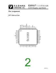
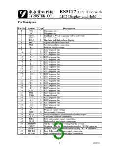
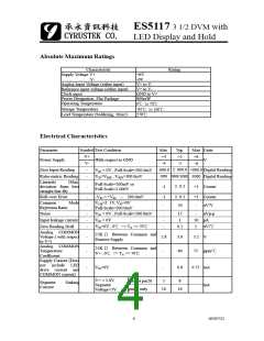
ES5117 3 1/2 DVM with
LED Display and Hold
3. System Timing
The oscillator frequency is divided by four prior to clocking the internal decade
counters. The signal integration takes a fixed 1000 counts time period which is equal to
4000 clock pulse. The back plane drive signal is derived by dividing oscillator
frequency by 800. To make a maximum noise rejection of line frequency(60Hz or
50Hz), the signal integration period should be a multiple of the line frequency period.
For 60Hz-noise rejection, oscillator frequencies of 120KHz, 80KHz, 60KHz, 48KHz,
40KHz, etc. should be selected. For 50Hz-noise rejection, oscillator frequencies of
100KHz, 50KHz 40KHz, etc. would be suitable.
For all rages of frequency Rosc should be 100KΩ, Cosc is selected form the
approximate equation f~0.45/RC. For 48KHz clock (3reading/second), Cosc=100pF.
4. Integrating Resistor
The input buffer amplifier and integrator are designed with class A output stages. The
output stage idling current is 100uA. Both of them can supply 20uA drive currents with
negligible linearity errors. The integrating resistor is chosen to remain linear drive
region in the output stage. It should not be so large that the leakage current of printed
circuit board will induce errors. The recommended integrating resistor value for the
200mV and 2V full-scale are 47KΩ and 470KΩ respectively.
5. Integrating Capacitor
The integrating capacitor should be selected to maximize integrator output voltage
swing without causing output saturation. For 3 readings/second (48KHz clock), a
0.22uF value of CINT is suggested. If a different oscillator frequency is used, CINT must
be changed in inverse proportion to maintain the nominal ± 2V integrator swing.
The integrating capacitor must have low dielectric absorption to minimize roll-
over error. An inexpensive polypropylene capacitor is recommended.
6. Auto-Zero Capacitor
The auto-zero capacitor size has some influence on system noise. A 0.47uF capacitor is
recommended for 200mV full scale. A 0.047uF capacitor is adequate for 2V full-scale
range applications. A mylar type dielectric capacitor is adequate.
7. Reference Voltage Capacitor
The reference voltage used to ramp the integrator output voltage back to zero during the
6
03/07/21

 CYRUSTEK [ Cyrustek corporation ]