CY8C24x23 Final Data Sheet
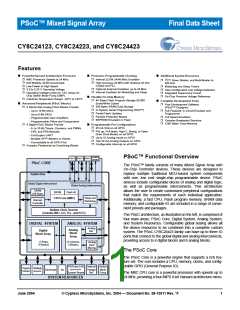
PSoC™ Overview
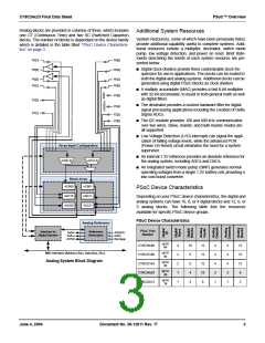
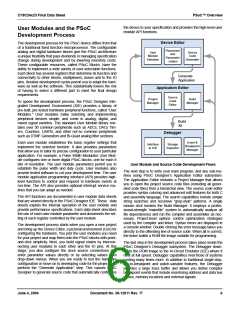
Analog blocks are provided in columns of three, which includes
one CT (Continuous Time) and two SC (Switched Capacitor)
blocks. The number of blocks is dependant on the device family
which is detailed in the table titled “PSoC Device Characteris-
tics” on page 3.
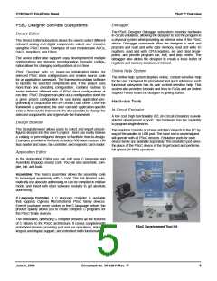
Additional System Resources
System Resources, some of which have been previously listed,
provide additional capability useful to complete systems. Addi-
tional resources include a multiplier, decimator, switch mode
pump, low voltage detection, and power on reset. Brief state-
ments describing the merits of each system resource are pre-
sented below.
P0[7]
P0[5]
P0[6]
P0[4]
■ Digital clock dividers provide three customizable clock fre-
quencies for use in applications. The clocks can be routed to
both the digital and analog systems. Additional clocks can be
generated using digital PSoC blocks as clock dividers.
P0[3]
P0[1]
P0[2]
P0[0]
■ A multiply accumulate (MAC) provides a fast 8-bit multiplier
with 32-bit accumulate, to assist in both general math as well
as digital filters.
P2[6]
P2[4]
P2[3]
P2[1]
■ The decimator provides a custom hardware filter for digital
signal processing applications including the creation of Delta
Sigma ADCs.
P2[2]
P2[0]
■ The I2C module provides 100 and 400 kHz communication
over two wires. Slave, master, and multi-master modes are
all supported.
■ Low Voltage Detection (LVD) interrupts can signal the appli-
cation of falling voltage levels, while the advanced POR
(Power On Reset) circuit eliminates the need for a system
supervisor.
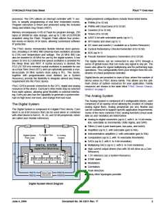
Array Input Configuration
■ An internal 1.3V reference provides an absolute reference for
ACI0[1:0]
ACI1[1:0]
the analog system, including ADCs and DACs.
■ An integrated switch mode pump (SMP) generates normal
operating voltages from a single 1.2V battery cell, providing a
low cost boost converter.
Block Array
ACB00
ASC10
ASD20
ACB01
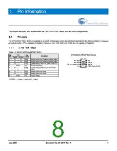
PSoC Device Characteristics
ASD11
ASC21
Depending on your PSoC device characteristics, the digital and
analog systems can have 16, 8, or 4 digital blocks and 12, 6, or
3 analog blocks. The following table lists the resources
available for specific PSoC device groups.
PSoC Device Characteristics
Analog Reference
PSoC Part
Number
Interface to
Digital System
Reference
Generators
RefHi
RefLo
AGND
AGNDIn
RefIn
Bandgap
up to
64
CY8C29x66
CY8C27x66
CY8C27x43
CY8C24x23
CY8C22x13
4
2
2
1
1
16
8
12
12
12
12
8
4
4
4
2
1
4
4
4
2
1
12
12
12
6
up to
44
M8C Interface (Address Bus, Data Bus, Etc.)
Analog System Block Diagram
up to
44
8
up to
24
4
up to
16
4
3
June 4, 2004
Document No. 38-12011 Rev. *F
3

 CYPRESS [ CYPRESS ]