BCM4330 Preliminary Data Sheet
FM Transmitter Specifications
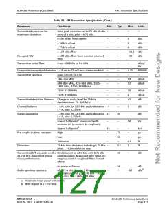
Section 17: FM Transmitter Specifications
Note: Values in this data sheet are design goals and are subject to change based on the results of
device characterization.
Unless otherwise stated, limit values apply for the conditions specified in Table 27: “Recommended Operating
Conditions and DC Characteristics,” on page 119. Typical values apply for the following conditions:
• Vbatt = 3.6V
• Ambient temperature +25°C
Table 31: FM Transmitter Specifications
Parameter
Conditions
Min
Typ
Max
Units
Synthesizer RF Parameters
Operating frequency
Frequency step
Settling time
Frequencies inclusive
Channel resolution
Single frequency switch in any direction –
to a frequency within the bands 88–108
MHz or 76–95 MHz. Time measured to
within 5 kHz of the final frequency.
76
–
50
–
108
40
MHz
kHz
ms
FM Rx/Tx antenna switching time –
–
5
–
–
ms/
channel
Frequency accuracy
Over temperature and voltage using
available reference clocks
–10
10
kHz
Transmitter Output
Maximum transmit output level Driving from a current source output into
a resonated loop antenna for which L =
120 nH nominal, with a Q ≥ 30, all Tx
frequencies ON, L= R = 0 (that is, no
modulation), 0 dB internal attenuation/
gain, and a 2.5V supply.
87.5–108 MHz 120
76–87.5 MHz 117
123
–
–
–
–
–
dBuV
dBuV
pF
Tuning capacitance range
76 to 108 MHz Based on tuning
inductance of 120 to 150 nH
–
a
Transmitter output accuracy
Gain step accuracy
Over entire output range
25 levels in normal 1 dB steps, one of
those being 0 dB
–2
–0.5
–
1
2
1.5
dB
dB
Pilot deviation
Relative to maximum peak deviation
8
–
10
%
®
BROADCOM
BCM4330 Preliminary Data Sheet
April 28, 2011 • 4330-DS304-RI
Page 126

 CYPRESS [ CYPRESS ]