12 EZ-USB Registers
12.1 Introduction
This section describes the EZ-USB registers in the order they appear in the EZ-USB mem-
ory map. The registers are named according to the following conventions.
Most registers deal with endpoints. The general register format is DDDnFFF, where:
DDD is endpoint direction, IN or OUT with respect to the USB host.
n
is the endpoint number, where:
•
•
•
“07” refers to endpoints 0-7 as a group.
0-7 refers to each individual BULK/INTERRUPT/CONTROL endpoint.
“ISO” indicates isochronous endpoints as a group.
FFF is the function, where:
•
•
•
•
CS is a control and status register
IRQ is an Interrupt Request bit
IE is an Interrupt Enable bit
BC, BCL, and BCH are byte count registers. BC is used for single byte counts,
and BCL/H are used as the low and high bytes of 16-bit byte counts.
•
•
DATA is a single-register access to a FIFO.
BUF is the start address of a buffer.
Examples:
•
•
•
IN7BC is the Endpoint 7 IN byte count.
OUT07IRQ is the register containing interrupt request bits for OUT endpoints 0-7.
INISOVAL contains valid bits for the isochronous IN endpoints (EP8IN-EP15IN).
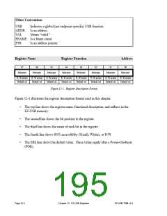
EZ-USB TRM v1.9
Chapter 12. EZ-USB Registers
Page 12-1

 CYPRESS [ CYPRESS ]