Additional Resources: Product Page
|
3D Model
CUI Devices │ SERIES: CFM-60V │ DESCRIPTION: DC AXIAL FAN
date 02/11/2020 │ page 13 of 15
APPLICATION NOTES
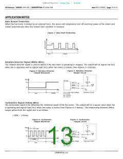
Auto Restart Protection
When the fan motor is locked by an external force, the device will temporarily turn off electrical power to the motor and
restart automatically when the locked rotor condition is released.
Figure 1: Auto Start Protection
t
Run
Locked
Rotation Detector Signal (White Wire)
The rotation detector signal is used to detect if the fan motor is operating or stopped. The output will be logical low (VL)
when fan is operating and be logical high (Vcc) when fan motor is locked. (See Figures 2~3 below).
Figure 3: Rotation Detector
Output Circuit
Figure 2: Rotation Detector
Output Waveform
Vcc
Vsig
Vcc
DC Fan
Ic
RL
Red (+)
Vsig
White
VL
Black (-)
t
Vcc ≤ max input voltage
Ic ≤ 4 mA
Customer Circuit
Locked
Run
RL ≥ Vcc/Ic
VL ≤ 0.5 V
Tachometer Signal (Yellow Wire)
The tachometer signal is for detecting the rotational speed of the fan motor. The output will be a square wave when fan
is operating and logical high (Vcc) when fan motor is locked (See Figures 4~5 below). The relationship between RPM &
output pulses from the signal wire is as follows.
1 RPM = 2 Pulses
Figure 4: Tachometer
Output Waveform
Figure 5: Tachometer
Output Circuit
Vcc
Vsig
Vcc
1 Pulse
DC Fan
Ic
RL
Red (+)
Vsig
Yellow
VL
Black (-)
1 RPM
Run
t
Vcc ≤ max input voltage
Ic ≤ 4 mA
Customer Circuit
Locked
RL ≥ Vcc/Ic
VL ≤ 0.5 V
cuidevices.com

 CUI [ CUI INC ]