CM119B
USB Audio Single Chip
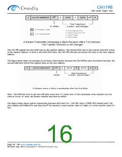
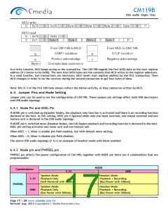
In a write transfer, MCU keeps acting as the transmitter. The CM119B regards the first DATA byte as the start register
address (it’s better to be 0x00). The next four DATA bytes are the contents that MCU writes to the register addresses.
In a read transfer, two transactions are necessary. MCU resets start register address by the first transaction. Then
MCU changes in order to be the receiver during the second transaction to get four bytes of data.
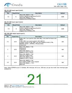
Note: Bits 0~3 of the first HID byte always reflect the button activity, so they cannot be written by MCU.
6.4 Jumper Pins and Mode Setting
Jumper pins can be used to set the configuration of CM119B. These jumper pin settings affect both USB descriptors
and USB audio topology.
6.4.1 Mode Pin and MSEL Pin
If MODE pin is switched up (Speaker Mode), the playback only function is activated and there is no recording function
declared to the host. At this setting, MSEL pin is ignored while only one input terminal, one output terminal and one
feature unit is declared in the USB audio topology.
If MODE pin is switched down (Headset Mode), the full duplex playback and recording function is declared to the host.
MSEL pin setting activates one mixer unit and one feature unit.
When MSEL = 1, Mixer is enable (AA-Path enable), but with default mute setting;
When MSEL = 0, Mixer is disable (AA-Path disable).
The above USB audio topology (7.1) is an example of headset mode with Mixer enabled.
6.4.2 Mode pin and PWRSEL pin
PWRSEL pin affects the power configuration of CM119B; together with MODE pin there are 4 combinations that are
programmable.
MODE
Combinations
3.3V
GND
Speaker Mode:
Playback Only
(Self-Powered with 100mA)
Headset Mode:
Playback + Recording
(Bus Power with 100mA)
3.3V
GND
PWRSEL
Speaker Mode:
Playback Only
(Bus Power with 500mA)
Headset Mode:
Playback + Recording
(Bus Power with 500mA)
Page 17 / 29 www.cmedia.com.tw
Revised: Aug. 2013 Copyright© C-Media Electronics Inc.

 CMEDIA [ C-MEDIA ELECTRONICS ]