CM119B
USB Audio Single Chip
6.3 MCU Interface
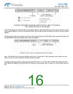
On MCU serial interface, the CM119B functions as a slave device with bit rate up to 400Kbps (fast mode). MCU can
read/write 3 bytes to the CM119B device with a 2-bit register address. Since host side and MCU can both access all of
the internal registers, access contention should be avoided on application when both try to access the same register.
The7-bit slave address of the CM119B is assigned as 7’b0111000.
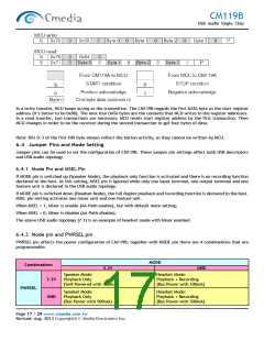
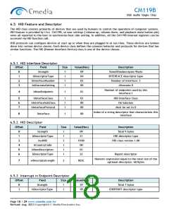
When a one-byte data is written by MCU, the CM119B will transfer totally 4 bytes to the USB host via an additional
interrupt pipe. The sequence of the upward HID report is given by: the button status first (address00); then register
with address01; followed by register with address02; lastly, register with address03. The USB host will keep polling
the upward HID report every 2mS. When there is any button pressed or released, or MCU data coming, the CM119B
will transfer the 4 bytes of HID report to the USB host again.
The CM119B can also transfer one byte MCU data from the USB host to its register. This is accomplished by a ‘Set
Output Report’ HID class request via default control pipe. MCU can get this downward byte by interrupt or polling.
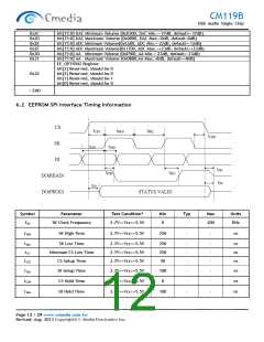
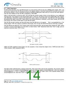
The CM119B has one input pin ‘SCLK’ where it gets serial clock from MCU, and one open-drain output pin ‘SDAT’ where
it sends or receives serial signal to or from MCU. As shown below, ‘SDAT’ should best able when ‘SCLK’ is high, and can
only have transition when ‘SCLK’ is low.
START and STOP conditions shown below are the exception. Every transaction begins from a STARTand ends with a
STOPor another START (repeated START).
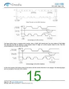
The figure below demonstrates a typical transaction. After every 8 bits sent by the transmitter, the receiver should
send one bit low for positive acknowledgement or one bit high for negative acknowledgement. After the negative
acknowledgement, a STOP or repeated START should follow. The next figure shows more detailed display about
acknowledgement bit. Note that ‘SCLK’ is always driven by the master.
Page 14 / 29 www.cmedia.com.tw
Revised: Aug. 2013 Copyright© C-Media Electronics Inc.

 CMEDIA [ C-MEDIA ELECTRONICS ]