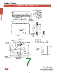
CCM02 Series
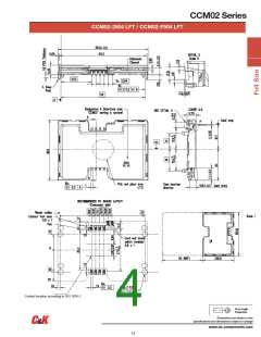
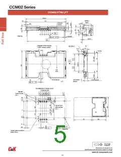
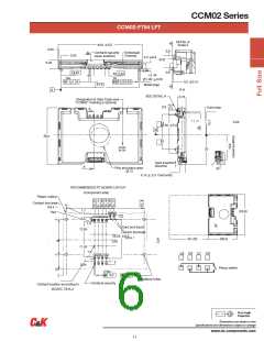
CCM02-F796 LFT
55,6 0,2
54,3
DETAIL A
Scale 5
0.65
Embossed
Channel
2,05
5x
2,54
4x
4 Metal Pegs
ø 1,62 0,05
ø 0,2
A
B
0,2 0,15
51,5
Designation & Date-Code area
"CCM02" marking is optional
A-A
SEE DETAIL A
5,75
A
Card stop
F796T
XX XX
A
Card insertion
direction
Pick and place area
4,15 0,3 Card entry
10x
0,3
ø 13
1
A
RECOMMENDED PC BOARD LAYOUT
(Component side)
Plastic outline
Contact foot area
0,8 x 1
SW SW
Pad
C1 C2 C3 C4
14
Card end travel
switch terminals
0,8 x 1
0
10
(50)
(38,5)
C5 C6 C7 C8
10x
20
+0,1
0
4x
1,9
ø
2,05
1,3
0,2
ø 0,1
Metallized holes
Contact location according to
ISO/IEC 7816-2
Dimensions are shown in mm
Specifications and dimensions subject to change
www.ck-components.com
16

 CK-COMPONENTS [ C&K COMPONENTS ]