P r o d u c t I n n o v a t i o n F r o m
PA85 • PA85A
GENERAL
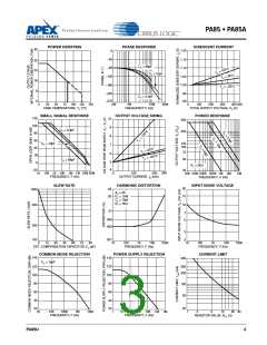
SAFEꢀOPERATINGꢀCURVES
PleasereadApplicationNoteꢀ"GeneralOperatingConsider-
ations"whichcoversstability,supplies,heatsinking,mounting,
currentlimit,SOAinterpretation,andspecificationinterpretation.
Visit www.Cirrus.com for design tools that help automate tasks
such as calculations for stability, internal power dissipation,
current limit and heat sink selection. The "Application Notes"
and "Technical Seminar" sections contain a wealth of informa-
tion on specific types of applications. Package outlines, heat
sinks, mounting hardware and other accessories are located
in the "Packages and Accessories" section. Evaluation Kits
are available for most Apex Precision Power product models,
consult the "Evaluation Kit" section for details. For the most
currentversionofallApexPrecisionPowerproductdatasheets,
visit www.Cirrus.com.
The safe operating area curves define the maximum ad-
ditional internal power dissipation the amplifier can tolerate
when it produces the necessary output to drive an external
load. This is not the same as the absolute maximum internal
powerdissipationlistedelsewhereinthespecificationsincethe
quiescentpowerdissipationissignificantcomparedtothetotal.
INPUTꢀPROTECTION
Although the PA85 can withstand differential voltages up to
±25V, additional external protection is recommended. Since
the PA85 is a high speed amplifier, low leakage, low capaci-
tance JFETs connected as diodes are recommended (e.g.
2N44ꢀ6, Qꢀ-Q4 in Figure 2). The differential input voltage will
be clamped to ±ꢀ.4V. This is sufficient overdrive to produce
maximum power bandwidth.
CURRENTꢀLIMIT
POWERꢀSUPPLYꢀPROTECTION
For proper operation, the current limit resistor (RCL) must be
connected as shown in the external connection diagram. The
minimum value is ꢀ.4 ohm, however for optimum reliability the
resistor value should be set as high as possible. The value
is calculated as follows; with the maximum practical value of
30 ohms.
Unidirectionalzenerdiodetransientsuppressorsarerecom-
mended as protection on the supply pins. The zeners clamp
transients to voltages within the power supply rating and also
clamp power supply reversals to ground. Whether the zeners
are used or not, the system power supply should be evaluated
for transient performance including power-on overshoot and
power-off polarity reversals as well as line regulation.
.7
RCL
=
ILIM - .0ꢀ6
Conditionswhichcancauseopencircuitsorpolarityreversals
on either power supply rail should be avoided or protected
against. Reversals or opens on the negative supply rail is
known to induce input stage failure. Unidirectional transzorbs
prevent this, and it is desirable that they be both electrically
and physically as close to the amplifier as possible.
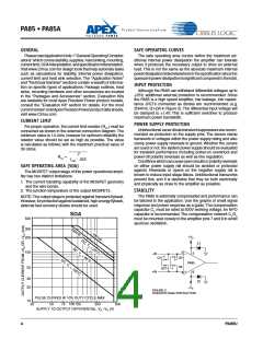
SAFEꢀOPERATINGꢀAREAꢀ(SOA)
The MOSFET output stage of this power operational ampli-
fier has two distinct limitations:
ꢀ. The current handling capability of the MOSFET geometry
and the wire bonds.
STABILITY
2. The junction temperature of the output MOSFETs.
The PA85 is externally compensated and performance can
be tailored to the application. Use the graphs of small signal
response and power response as a guide.The compensation
capacitor CC must be rated at 500V working voltage.An NPO
capacitor is recommended. The compensation network CCRC
must be mounted closely to the amplifier pins 7 and 8 to avoid
spurious oscillation.
NOTE:The output stage is protected against transient flyback.
However,forprotectionagainstsustained,highenergyflyback,
external fast-recovery diodes should be used.
SOA
500
200mS
300
+VS
Z1
200
5
100
3
PA85
6
–IN
+IN
Q1
Q3
DC, T
C
= 125°C
Q4
50
Q2
4
30
20
Z2
–VS
FIGURE 2.
OVERVOLTAGE PROTECTION
PULSE CURVES @ 10% DUTY CYCLE MAX
10
25
50
75 100125
250
500
SUPPLY TO OUTPUT DIFFERENTIAL, VS –VO (V)
4
PA85U

 CIRRUS [ CIRRUS LOGIC ]