P r o d u c t I n n o v a t i o n F r o m
PA85 • PA85A
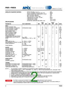
SUPPLY VOLTAGE, +VS to –VS
450V
200mA
30W
ABSOLUTEꢀMAXIMUMꢀRATINGS
OUTPUT CURRENT, continuous within SOA
POWER DISSIPATION, continuous @ TC = 25°C2
INPUT VOLTAGE, differential
±25V
INPUT VOLTAGE, common mode
TEMPERATURE, pin solder - ꢀ0s max
TEMPERATURE, junction2
±VS
300°C
ꢀ50°C
TEMPERATURE, storage
OPERATING TEMPERATURE RANGE, case
–65 to +ꢀ50°C
–55 to +ꢀ25°C
SPECIFICATIONS
PA85
TYP
PA85A
TYP
PARAMETER
TEST CONDITIONS1
MIN
MAX
MIN
MAX
UNITS
INPUT
OFFSET VOLTAGE, initial
OFFSET VOLTAGE, vs. temperature
OFFSET VOLTAGE, vs. supply
OFFSET VOLTAGE, vs. time
BIAS CURRENT, initial3
BIAS CURRENT, vs. supply
OFFSET CURRENT, initial3
INPUT IMPEDANCE, DC
INPUT CAPACITANCE
.5
ꢀ0
3
75
5
.0ꢀ
ꢀ0
ꢀ0ꢀꢀ
4
2
30
ꢀ0
.25
5
*
*
3
*
3
*
*
.5
ꢀ0
*
mV
µV/°C
µV/V
µV/√kh
pA
pA/V
pA
Ω
pF
V
dB
Full temperature range
50
ꢀ0
30
ꢀ00
COMMON MODE VOLTAGE RANGE4
COMMON MODE REJECTION, DC
NOISE
±VS–ꢀ5
±0
*
*
VCM = ±±0V
ꢀ00kHz BW, RS = ꢀKΩ, CC = ꢀ0pf
ꢀꢀ0
ꢀ
*
*
µVrms
GAIN
OPEN LOOP, @ ꢀ5Hz
R = 2KΩ, C = OPEN
±6
ꢀꢀꢀ
ꢀ00
300
500
60
*
*
*
*
*
*
dB
MHz
kHz
kHz
°
GAIN BANDWIDTH PRODUCT at ꢀMHz RL = 2KΩ, CCC = 3.3pf
POWER BANDWIDTH
PHASE MARGIN
CL = ꢀ0pf
CCC = 3.3pf
Full temperature range
OUTPUT
VOLTAGE SWING4
VOLTAGE SWING4
VOLTAGE SWING4
CURRENT, continuous
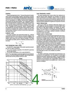
SLEW RATE, A = 20
SLEW RATE, AVV = ꢀ00
CAPACITIVE LOAD, AV = +ꢀ
SETTLING TIME to .ꢀ%
RESISTANCE, no load
I = ±200mA
IO = ±75mA
±Vs–ꢀ0 ±Vs–6.5
±V–8.5 ±Vs–6.0
±V–8.0 ±Vs–5.5
±200
400
ꢀ000
470
ꢀ
*
*
*
*
*
*
*
*
*
V
V
V
mA
V/µs
V/µs
pf
IOO = ±20mA
T = 85°C
CC = ꢀ0pf
CCC = OPEN
700
*
Full temperature range
CC = ꢀ0pf, 2V step
RCL = 0
*
*
*
µs
Ω
50
POWER SUPPLY
VOLTAGE6
CURRENT, quiescent
Full temperature range
±ꢀ5
±ꢀ50
2ꢀ
±225
25
*
*
*
*
*
V
mA
THERMAL
RESISTANCE, AC, junction to case5
RESISTANCE, DC, junction to case
RESISTANCE, junction to air
TEMPERATURE RANGE, case
Full temperature range, F > 60Hz
Full temperature range, F < 60Hz
Full temperature range
2.5
4.2
*
*
°C/W
°C/W
°C/W
°C
30
*
Meets full range specifications
–25
+85
*
*
NOTES:
*
The specification of PA85A is identical to the specification for PA85 in applicable column to the left.
ꢀ. Unless otherwise noted: TC = 25°C, compensation = CC = 68pF, RC = ꢀ00Ω. DC input specifications are ± value given. Power
supply voltage is typical rating.
2. Long term operation at the maximum junction temperature will result in reduced product life. Derate internal power dissipation to
achieve high MTTF. Ratings apply only to output transistors. An additional ꢀ0W may be dissipated due to quiescent power.
3. Doubles for every ꢀ0°C of temperature increase.
4. +V and –VS denote the positive and negative power supply rail respectively.
5. RaSting applies if the output current alternates between both output transistors at a rate faster than 60Hz.
6. Derate max supply rating .625 V/°C below 25°C case. No derating needed above 25°C case.
The PA85 is constructed from MOSFET transistors. ESD handling procedures must be observed.
CAUTION
The internal substrate contains beryllia (BeO). Do not break the seal. If accidentally broken, do not crush, machine, or
subject to temperatures in excess of 850°C to avoid generating toxic fumes.
2
PA85U

 CIRRUS [ CIRRUS LOGIC ]