|
3
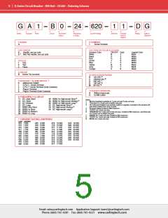
G-Series Circuit Breaker - DIN Rail – General Specifications
Electrical Tables
Table A: Lists UL Recognized, CSA Accepted and TUV Certified capabilities as a Component Supplementary Protector.
G-SERIES TABLE A: COMPONENT SUPPLEMENTARY PROTECTORS
Voltage
Current Rating Short Circuit Capacity (Amps)
Circuit
Max
Rating
80
240
240
480
Minimum
Full Load
Amps
Without Backup Fuse
Application Codes
Configuration
Frequency Phase
Poles
UL/CSA
3000
3000
3000
1500
TUV
UL
CSA
DC
---
1
1
1
2
3
.1 - 63
.1 - 63
.1 - 63
.1 - 63
1500
1500
1500
TC1, OL1, U1 TC1, OL1, U1
TC1, OL1, U1 TC1, OL1, U1
TC1, OL1, U1 TC1, OL1, U1
50 / 60
50 / 60
50 / 60
Series
1
3
415V, 1000 TC1, OL1, U1 TC1, OL1, U1
Table B: Lists UL Listed (489) configuration and performance capabilities.
G-SERIES TABLE B: UL 489 LISTED BRANCH CIRCUIT BREAKERS
Interrupting Capacity
(Amps RMS)
Circuit
Voltage
Current Rating
Full Load Amps
1 - 50
Configuration
Max Rating Frequency Phase
Poles
80
DC
---
---
1
1
5000
5000
5000
5000
125
DC
2
1 - 50
120
50 / 60
50 / 60
1
1 - 50
Series
120 / 240
1
1 - 31
1 - 50
240
50 / 60
1
1
1 - 25
5000
1
One pole out of the three poles must be a neutral break.
Electrical
Mechanical
Maximum Voltage
AC: 240VAC (single pole),
Endurance
10,000 ON-OFF operations @ 6 per
minute; with rated current & voltage.
All G-Series circuit breakers will
trip on overload, even when actuator
is forcibly held in the ON position.
The operating actuator moves
480VAC (3 poles, additional pole
shall be dedicated for neutral break)
DC: 80VDC (single pole & multipole)
0.1 – 63A. Other ratings available,
see Ordering Scheme.
Trip Free
Current Rating
Trip Indication
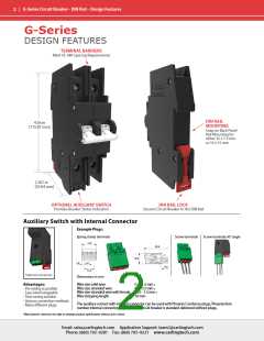
Auxiliary Switch Rating (optional) Integrated, load side.
SPST, 3A – 125VAC, 2A – 30VDC.
Auxiliary switch senses the on & off
position of circuit breaker handle,
as well as contact arm position.
Switch connections are screw
positively to the OFF position when
an overload causes the breaker to
trip. With mid-trip, the handle moves
to the mid position on electrical trip
of the circuit breaker. With mid trip
handle with alarm switch, handle
moves to the mid position and the
alarm switch actuates when the
circuit breaker is electrically tripped.
terminals.
Insulation Resistance
Dielectric Strength
Minimum of 100 Megohms at 500 VDC
UL, CSA: 1960 V 50/60 Hz for one
minute between all electrically
isolated terminals. G-Series circuit
breakers comply with the 8mm
spacing and 3750V 50/60 Hz dielectric
requirements from hazardous
voltage to operator accessible
surfaces, between adjacent poles
and from main circuits to auxiliary
circuits per Publications EN 60950
and VDE 0805.
Physical
Number of Poles
Weight
1 pole ≤ 63A, 2 poles ≤ 63A per pole
Approx.172 grams/pole ( 4.13 oz).
Housing: Black
Standard Colors
Environmental
Designed in accordance with requirements of specification
MIL-PRF-55629 & MIL-STD-202 as follows:
Shock
Withstands 100 Gs, 6ms sawtooth
while carrying rated current per
Method 213, Test Condition “I”.
Instantaneous and ultrashort curves
tested @ 90% of rated current.
Withstands 0.060” excursion from
10-55 Hz & 10 Gs 55-500 Hz, @
rated current per Method 204C, Test
Cond. A. Instantaneous & ultrashort
curves tested @ 90% of rated
current.
Method 106D, i.e., ten 24-hour
cycles @ +25°C to +65°C, 80-98% RH.
Method 101, Condition A (90-95%
RH @ 5% NaCl Solution, 96 hrs).
Method 107D, Condition A (five cycles
@ -55°C to +25°C to +85°C to +25°C).
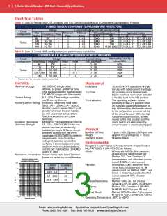
Resistance, Impedance Values from Line to Load Terminal -
based on series trip circuit breaker.
RESISTANCE, IMPEDANCE VALUES
from Line to Load Terminals
(Values Based on Series Trip Circuit Breaker)
1000
Vibration
CURRENT
(AMPS)
TOLERANCE
(%)
100
10
0.10 - 5.0
5.1 - 20.0
20.1 - 63.0
15
25
35
O
H
M
S
1
Moisture Resistance
Salt Spray
0.1
0.01
Thermal Shock
0.001
0.01
0.1
1
10
100
Operating Temperature -40°C to +85°C
AMPERE RATING
Email: sales@carlingtech.com Application Support: team2@carlingtech.com
Phone: (860) 793–9281 Fax: (860) 793–9231 www.carlingtech.com

 Carling Technologies [ Carling Technologies ]