|
F-Series Circuit Breaker – General Specifications
2
Electrical
Maximum Voltage
Current Ratings
Mechanical
125VDC, 277VAC
Endurance
4000 ON-OFF operations with rated
Current & Voltage & 4000
operations with no load (8000
operations total) @ 5 per minute.
Parallel Pole construction: 1000
operations with rated Current and
Voltage @ 5 per minute.
All F-Series Circuit Breakers will trip
on overload, even when the
actuator is forcibly held in the ON
position.
The operating actuator moves
positively to the OFF position when
an overload causes the circuit
breaker to trip.
Standard current coils: 100, 125,
150, 175, 225, 250 amps. 300,
350, 400, 500, 600, 700 amps
available as parallel pole
construction.
Auxiliary Switch Rating SPDT; 10.1 Amps @ 250VAC, 1.0
Amps @ 65VDC, 0.5 Amps @
Trip Free
80VDC 0.1 Amps @ 125VAC (with
gold contacts).
Minimum: 100 Megohms at 500
VDC
Insulation Resistance
Dielectric Strength
Trip Indication
1960 VAC, 50/60 Hz for one
minute between all electrically
isolated terminals, except 2500
VAC for one minute between
alarm/aux. switch and main
terminals with contacts in open
and closed position. F-Series
circuit breakers comply with the
8mm spacing & 3750VAC 50/60
Hz dielectric requirements from
hazardous voltage to operator
accessible surfaces, between
adjacent poles and from main
circuits to auxilary circuits per
Publications EN 60950 and VDE
0805.
Physical
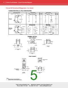
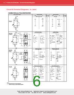
Number of Poles
1 - 3 Poles Note: Ratings over 250
Amps only available with parallel
pole.
Internal Circuit Config. Series (with or without auxiliary
switch), Switch Only (with or without
auxiliary switch).
Available Accessories Factory installed: DC Current
Metering Shunt (25 mV @lr)
Weight
Varies depending on construction.
Consult factory.
Housing - Black; Actuator- Black or
White with contrasting ON-OFF
legend.
Standard Colors
Resistance, Impedance Values from Line to Load Terminal
- based on Series Trip Circuit
Breaker.
Environmental
Designed and tested in accordance with requirements of
specification MIL-PRF-55629 & MIL-STD-202 as follows:
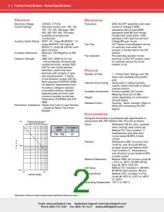
RESISTANCE PER POLE VALUES
from Line to Load Terminals
(Values Based on Series Trip Circuit Breaker)
Shock
Withstands 100 Gs, 6ms, sawtooth
while carrying rated current per
Method 213, Test Condition “I”.
Instantaneous and ultra-short
curves tested @ 90% of rated
current.
CURRENT
(AMPS)
TOLERANCE
(%)
100 - 700
50
Vibration
Withstands 0.060” excursion from
10-55 Hz, and 10 Gs 55-500 Hz,
at rated current per Method 204C,
Test Condition A. Instantaneous
and ultrashort curves tested at 90%
of rated current.
Moisture Resistance
Method 106D; ten 24-hour cycles @
+ 25°C to +65°C, 80-98% RH.56
days @ +85°C, 85% RH.
Salt Spray
Method 101, Condition A (90-95%
RH @ 5% NaCl Solution, 96 hrs).
Method 107D, Condition A (Five
cycles @ -55°C to +25°C to +85°C
to +25°C).
Thermal Shock
Operating Temperature -40° C to +85° C
*Manufacturer reserves the right to change product specification without prior notice.
Email: sales@carlingtech.com Application Support: team2@carlingtech.com
Phone: (860) 793–9281 Fax: (860) 793–9231 www.carlingtech.com

 Carling Technologies [ Carling Technologies ]