|
25
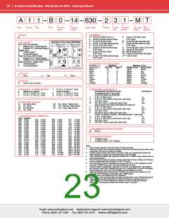
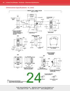
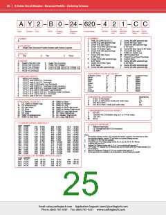
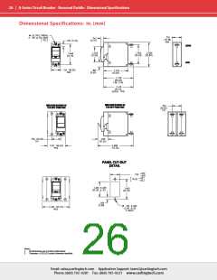
A-Series Circuit Breaker - Recessed Paddle – Ordering Scheme
A Y 2 B 0 24 620 4 2 1 C C
8
9
10
Mounting/
Barriers
11
12
1
2
3
4
5
6
7
Terminal
Actuator
Color
Max. Appl. Agency
Rating Approval
Series
Actuator
Poles
Circuit
Auxiliary
Switch
Frequency
& Delay
Current Rating
8 TERMINAL
1 SERIES
A
1
2
3
4
5
6
Push-On 0.250 Tab (Q.C.)
Screw 8-32 with upturned lugs
Screw 8-32 (Bus Type)
Screw 10-32 with upturned lugs
Screw 10-32 (Bus Type)
Screw 8-32 with upturned lugs
& 30° bend
C
E
F
Screw, M4 with upturned lugs
Screw, M4 (Bus Type)
Screw M5 with upturned lugs
& 30° bend
Screw M5 (Bus Type) & 30° bend
Screw M5 (Bus Type)
0.250 Q.C./Solder Lug
M6 Threaded Stud
Printed Circuit Board Terminals
Push-In Stud
Screw, M4 with upturned lugs
& 30° Bend
1
2 ACTUATOR
Y
Single Color Recessed Paddle Actuator with Vertical Legends
G
H
L
M
P
Q
R
2
3 POLES
One
7
8
9
B
Screw 8-32 (Bus Type)
& 30° bend
Screw 10-32 with upturned lugs
& 30° bend
Screw 10-32 (Bus Type)
& 30° bend
Screw M5 with upturned lugs
1
2
Two
3
Three
4 CIRCUIT
A
B
C
D
E
Switch-Only (No Coil)
F
Relay Trip (Current)
Relay Trip (Voltage)
Series Trip (Current)
Series Trip (Voltage)
Shunt Trip (Current)
Shunt Trip (Voltage)
G
H
K
S
T
Screw, M5 with upturned lugs
Screw, M4 with upturned lugs
Dual Coil with Shunt Trip Voltage Coil
Dual Coil with Shunt Trip Current Coil
5
9 ACTUATOR COLOR & LEGEND
Actuator Color
White
I-O
A
C
F
H
K
M
P
ON-OFF
Dual
Legend Color
Black
5 AUXILIARY SWITCH
B
D
G
J
1
2
3
4
5
6
7
8
0
1
2
3
4
5
6
7
8
9
without Aux Switch
Black
White
S.P.D.T. with 0.093 Q.C. Terminals
Red
White
S.P.D.T. with 0.110 Q.C. Terminals
Green
Blue
Yellow
Gray
White
S.P.D.T. with 0.139 Solder Lug Terminals
S.P.D.T. with 0.093 Q.C. Terminals (Gold Contacts)
S.P.D.T. with 0.093 Q.C. Terminals (Gold Contacts)
S.P.S.T.-N.O. with 0.139 Solder Lug Terminals
S.P.S.T.-N.O. with 0.110 Q.C. Terminals (Gold Contacts)
S.P.S.T.-N.O. with 0.187 Q.C. Terminals
S.P.D.T. with 0.187 Q.C. Terminals
L
White
N
Q
S
Black
Black
Orange
R
Black
10 MOUNTING / BARRIERS
BARRIERS
1
6-32 x 0.195 inches
no
A
2
B
6-32 X 0.195 inches (multi-pole units only)
ISO M3 x 5mm
yes
no
3
6 FREQUENCY & DELAY
22 50/60 Hz Short
3
DC, 50/60 Hz Switch Only
24 50/60 Hz Medium
ISO M3 x 5mm (multi-pole units only)
yes
10 DC Instantaneous
11 DC Ultra Short
12 DC Short
26 50/60 Hz Long
42 50/60 Hz Short High-inrush
44 50/60 Hz Medium High-inrush
46 50/60 Hz Long High-inrush
52 DC, Short, High-inrush
54 DC, Medium, High-inrush
56 DC, Long, High-inrush
6
11 MAXIMUM APPLICATION RATING
14 DC Medium
A
C
K
M
65 VDC
16 DC Long
120/240 VAC (Available only on 2 or 3-Pole units)
20 50/60 Hz Instantaneous
21 50/60 Hz Ultra Short
120 VAC
80 DC
4
7 CURRENT RATING (AMPERES)
7
12 AGENCY APPROVAL
CODE AMPERES
A
C
T
Without Approvals
220 0.200
225 0.250
230 0.300
235 0.350
240 0.400
245 0.450
250 0.500
255 0.550
260 0.600
265 0.650
270 0.700
275 0.750
280 0.800
285 0.850
290 0.900
295 0.950
410 1.000
512 1.250
415 1.500
517 1.750
420 2.000
522 2.250
425 2.500
527 2.750
430 3.000
435 3.500
440 4.000
445 4.500
450 5.000
455 5.500
460 6.000
465 6.500
470 7.000
475 7.500
480 8.000
485 8.500
490 9.000
495 9.500
610 10.000
710 10.500
611 11.000
711 11.500
612 12.000
712 12.500
613 13.000
614 14.000
615 15.000
616 16.000
617 17.000
618 18.000
620 20.000
622 22.000
624 24.000
625 25.000
630 30.000
635 35.000
640 40.000
645 45.000
650 50.000
UL Recognized and CSA Accepted
UL 489A
Notes:
1
All standard catalog numbers are supplied with Vertical Legends. For Horizontal or other
non-standard legends, choose “X” and order as a special catalog number.
For rating (T) 2 & 3 Pole not available.
Frequency and Time Delay ratings of (03, 20, 21, 22, 24, 26, 42, 44, 46) not
available with approval T.
Voltage Coil Ratings starting with (J, K, or L) not available with approval T.
“OFF and/or “O” Legends are on Bracket and are only visible when the Paddle Actuator is in
the off position.
Maximum Application Ratings (C & K) not available with approval T.
Not all approvals are available in all constructions. Consult factory for details.
2
3
4
5
6
7
OR VOLTAGE COIL (NORMAL RATED VOLTAGE)
CODE AMPERES
A06
6 DC
A32 32 DC
A48 48 DC
A65 65 DC
J12 12 AC
J18 18 AC
J24 24 AC
J48 48 AC
J65
65 AC
A12 12 DC
A18 18 DC
A24 24 DC
K20 120 AC
L40 240 AC
J06
6 AC
Email: sales@carlingtech.com Application Support: team2@carlingtech.com
Phone: (860) 793–9281 Fax: (860) 793–9231 www.carlingtech.com

 Carling Technologies [ Carling Technologies ]