LH0033 / LH0033C
CORPORATION
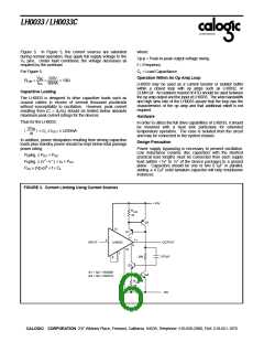
Figure 3. In Figure 3, the current sources are saturated
during normal operation, thus apply full supply voltage to the
VC pins. Under fault conditions, the voltage decreases as
required by the overload.
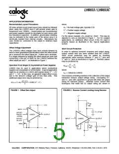
where:
Vp-p = Peak-to-peak output voltage swing
f = Frequency
For Figure 5:
CL = Load Capacitance
Operation Within An Op Amp Loop
VBE
ISC 60mA
0.6V
RLIM
=
=
= 10Ω
LH0033 may be used as a current booster or isolator buffer
within a closed loop with op amps such as LH0032, or
CLM4124. An isolation resistor of 47Ω should be used between
the op amp output and the input of LH0033. The wide bandwidth
and high slew rate of the LH0033 assure that the loop has the
characteristics of the op amp and that additional rolloff is not
required.
Capacitive Loading
The LH0033 is designed to drive capacitive loads such as
coaxial cables in excess of several thousand picofarads
without susceptibility to oscillation. However, peak current
resulting from (C × dV/dt) should be limited below absolute
maximum peak current ratings for the devices.
Hardware
Thus for the LH0033:
In order to utilize the full drive capabilities of LH0033, it should
be mounted with a heat sink particulary for extended
temperature operation. The case is isolated from the circuit
and may be connected to the system chassis.
∆V
IN
(
) × CL ≤ IOUT ≤ ±250mA
∆t
In addition, power dissipation resulting from driving capacitive
loads plus standby power should be kept below total package
power rating:
Design Precaution
Power supply bypassing is necessary to prevent oscillation.
Low inductance ceramic disc capacitors with the shortest
practical lead lengths must be connected from each supply
lead (within <1⁄4" to 1⁄2" of the device package) to a ground
plane. Capacitors should be one or two 0.1µF in parallel;
adding a 4.7µF solid tantalum capacitor will help troublsome
instances.
PDpkg. ≥ PDC + PAC
PDpkg. ≥ (V+–V–) × IS + PAC
PAC (Vp-p)2 × f × CL
FIGURE 3. Current Limiting Using Current Sources
+15V
RLIM
10
Q2
12
Q1
1
5
11
INPUT
LH0033
OUTPUT
9
10
7
0.01µF
30k
6
Q3
Q1 = Q2 = 2N2905
Q3 = Q4 = 2N2219
Q4
RLIM
10
-15V
CALOGIC CORPORATION, 237 Whitney Place, Fremont, California 94539, Telephone: 510-656-2900, FAX: 510-651-1076

 CALOGIC [ CALOGIC, LLC ]