Data Sheet
iꢆꢅꢄgꢃꢂꢁ lꢇꢆꢄꢂꢃꢇꢅy eꢃꢃꢀꢃ (ile)
Specification Definitions
Linearity error refers to the deviation of each individual
code (normalized) from a straight line drawn from –FS
through +FS. The deviation is measured from the edge of
each particular code to the true straight line.
aꢉꢄꢃꢅꢊꢃꢄ Dꢄꢁꢂy
Aperture delay represents the point in time, relative to
the rising edge of the CLOCK input, that the analog input
is sampled.
oꢊꢅꢉꢊꢅ Dꢄꢁꢂy
aꢉꢄꢃꢅꢊꢃꢄ Jꢇꢅꢅꢄꢃ
Time between the clock’s triggering edge and output data
valid.
The variations in aperture delay for successive samples.
Dꢇꢋꢋꢄꢃꢄꢆꢅꢇꢂꢁ Gꢂꢇꢆ (DG)
ovꢄꢃvꢀꢁꢅꢂgꢄ rꢄꢌꢀvꢄꢃy tꢇmꢄ
A signal consisting of a sine wave superimposed on vari-
ous DC levels is applied to the input. Differential gain is
the maximum variation in the sampled sine wave ampli-
tudes at these DC levels.
The time required for the ADC to recover to full accuracy
after an analog input signal 125% of full scale is reduced
to 50% of the full-scale value.
sꢇgꢆꢂꢁ-tꢀ-nꢀꢇꢈꢄ rꢂꢅꢇꢀ (snr)
Dꢇꢋꢋꢄꢃꢄꢆꢅꢇꢂꢁ phꢂꢈꢄ (Dp)
The ratio of the fundamental sinusoid power to the total
noise power. Harmonics are excluded.
A signal consisting of a sine wave superimposed on vari-
ous DC levels is applied to the input. Differential phase is
the maximum variation in the sampled sine wave phases
at these DC levels.
sꢇgꢆꢂꢁ-tꢀ-nꢀꢇꢈꢄ aꢆd Dꢇꢈꢅꢀꢃꢅꢇꢀꢆ (sinaD)
The ratio of the fundamental sinusoid power to the total
noise and distortion power.
eꢋꢋꢄꢌꢅꢇvꢄ nꢊmbꢄꢃ oꢋ Bꢇꢅꢈ (enoB)
SINAD = 6.02N + 1.76, where N is equal to the effective
number of bits.
tꢀꢅꢂꢁ Hꢂꢃmꢀꢆꢇꢌ Dꢇꢈꢅꢀꢃꢅꢇꢀꢆ (tHD)
The ratio of the total power of the first 9 harmonics to the
power of the measured sinusoidal signal.
N = SINAD – 1.76
6.02
iꢆꢉꢊꢅ Bꢂꢆdwꢇdꢅh
sꢉꢊꢃꢇꢀꢊꢈ fꢃꢄꢄ Dyꢆꢂmꢇꢌ rꢂꢆgꢄ (sfDr)
Small signal (50mV) bandwidth (3dB) of analog input stage.
The ratio of the fundamental sinusoidal amplitude to the
single largest harmonic or spurious signal.
Dꢇꢋꢋꢄꢃꢄꢆꢅꢇꢂꢁ lꢇꢆꢄꢂꢃꢇꢅy eꢃꢃꢀꢃ (Dle)
Error in the width of each code from its theoretical value.
N
(Theoretical = V /2 )
FS
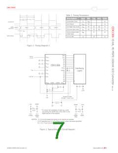
Figure 1. Timing Diagram 1
©2008 CADEKA Microcircuits LLC
www.cadeka.com
6

 CADEKA [ CADEKA MICROCIRCUITS LLC. ]