TM
Technical Specification
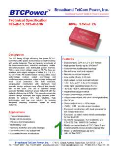
S25-48-3.3, S25-48-3.3N
48Vin 3.3Vout 7A
Remote Sense
Basic Operation And Functions
S25-48-3.3/S25-48-3.3N is
a
high efficiency,
The unit does NOT have remote sense pins.
isolated DC/DC converter. Neither heat sink nor
airflow is required when the unit operates at
ambient temperature of 25°C. The unit has basic
control, output adjustment and protection functions.
Output Trim (Pin 6)
Permits the user to adjust the output voltage up or
down to achieve the custom voltage or to make the
output voltage margining.
Input (Pin 2, Pin 3)
Input power Vin(+) must be connected to Positive
input pin 3; Input power Vin(-) must be connected to
Negative input pin2.
The unit’s output voltage can be adjusted up10% or
down 10% relative to the rated output voltage by
adding an external resistor between pin 6 and one
of the output pins (pin 4 and 5).
Output (Pin 4, Pin 6)
Output power Vout(+) must be connected to
Positive output pin 4; Output power Vout(-) must be
connected to Negative output pin6.
To increase the output voltage, a trim resistor
should be connected between pin 6(Trim) and pin 5
(Vout-), as shown in Fig 2.
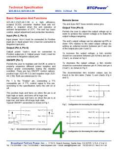
ON/OFF (Pin 1)
To decrease the output voltage, a trim resistor
should be connected between pin 6 (Trim) and pin 4
(Vout+), as shown in Fig 3.
Permits the user to maintain unit On/Off, in order to
properly sequence different power supplies and
reduce power consumption during the standby
condition. There are two ON/OFF control options:
positive logic (S25-48-3.3) and negative logic (S25-
48-3.3N). Both are referenced to Vin-.
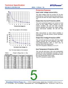
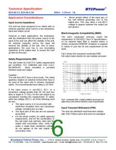
The recommended trim resistor values can be
found in the trim table (Table 1) and charts (Fig 4
and 5).
Pin 1 is the "Enable" pin, connecting a TTL
compatible pin. A TTL control signal to this pin,
according to the specification, turns the unit on or
off.
The positive logic unit turns on when the pin is at
logic high or open, and turns off at logic low.
The negative logic unit turns on when the pin is at
logic low, and turns off at logic high state.
Typical ON/OFF connection is shown in Fig 1.
Fig 2. Configuration for increasing the output voltage
Fig 1. Recommended ON/OFF circuit configuration
Fig 3. Configuration for decreasing the output voltage
Broadband TelCom Power, Inc. – 1719 S. Grand Avenue, Santa Ana, CA 92705 U.S.A. P 4 of 11
Tel.: 714-259-4888 • Fax: 714-259-0840 • www.btcpower.com • Email: sales@btcpower.com PS S25-48-3.3 Rev 3 16-1-04

 BTCPOWER [ BROADBAND TELCOM POWER, INC. ]