TM
Prelim. Specification
HBO80A-48-2.5
48Vin 2.5Vout 80A
Basic operation and functions
Pin 2 is the "Enable" pin, connecting a TTL
compatible pin. A TTL control signal to this pin,
according to the specification, will turn the unit on
or off.
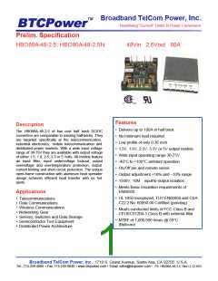
The HBO / HBP familyuses planar transformer
technology to achieve high output current. The
whole unit switches at the fixed frequency for a
predictable EMI performance. The HBO / HBP
Brick has many standard controls and protection
functions.
The positive logic version turns on when pin 2 is
at logic high, and turns off when pin 2 is at logic
low. The unit is on when pin 2 is left open.
Input Power ( pin1, pin4 )
The negative logic version turns on when pin 2 is
at logic low and turns off when pin 2 is at logic
high. The pin 2 can be directed to Vin(-), to
enable automatic turn on to the unit without the
need of an external control signal.
Input power Vin(+) must be connected to Positive
input voltage pin1; Input power Vin(-) must be
connected to Negative input voltage pin4.
Output Power ( pin9, pin5 )
Output power Vout(+) must be connected to
Positive output voltage pin9; Output power
Vout(-) must be connected to Negative output
voltage pin5.
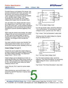
Remote Sense ( pin 8, pin 6 )
Permits the user to maintain the accurate output
voltage at the remote load terminals regardless of
the line drop.
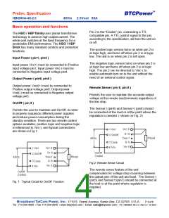
On/Off ( pin 2 )
The Sense(-) (pin6) and Sense(+) (pin8) should
be connected at the load or at the point where the
regulation is needed. ( shown on Fig. 2)
Permits the user to maintain unit On/Off, in order
to properly sequence different power supplies
and reduce power consumption during the
standby condition. There are two remote control
options available, positive logic and negative logic
is referenced to Vin(-), and typical connections
are shown in Fig 1.
Fig 2: Remote Sense Circuit
The remote sense feature of the unit
compensates for voltage drop occurring between
the output pins of the unit and load. The Sense(-)
(pin5) and Sense(+)(pin7) should be connected at
the load or at the point where regulation is
required.
Fig. 1: Typical Circuit for On/Off Function
Broadband TelCom Power, Inc. 1719 S. Grand Avenue, Santa Ana, CA 92705 U.S.A.
P 4 of 8
Tel.: 714-259-4888 • Fax: 714-259-0840 • www.btcpower.com • Email: sales@btcpower.com • PS HBO80A-48-2.5 Rev1.2 12-8-03

 BTCPOWER [ BROADBAND TELCOM POWER, INC. ]