PIN CONFIGURATION
ABSOLUTE MAXIMUM RATINGS(1)
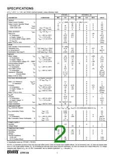
Power Supply, V+ (referenced to IO pin) .......................................... 40V
Input Voltage, VI+N, VI–N (referenced to IRET pin) .........................0V to V+
Storage Temperature Range ........................................ –55°C to +125°C
Lead Temperature (soldering, 10s) .............................................. +300°C
Output Current Limit ............................................................... Continuous
Junction Temperature ................................................................... +165°C
Top View
DIP and SOIC
1
2
3
4
5
6
7
VREG
14 VREF
5
NOTE: (1) Stresses above these ratings may cause permanent damage.
Exposure to absolute maximum conditions for extended periods may degrade
device reliability.
–
VIN
13 VREF2.5
RG
RG
12 Lin Polarity
11 RLIN
+
ELECTROSTATIC
DISCHARGE SENSITIVITY
This integrated circuit can be damaged by ESD. Burr-Brown
recommends that all integrated circuits be handled with
appropriate precautions. Failure to observe proper handling
and installation procedures can cause damage.
VIN
10 V+
IRET
IO
9
8
B (Base)
E (Emitter)
ESD damage can range from subtle performance degradation
to complete device failure. Precision integrated circuits may
be more susceptible to damage because very small parametric
changes could cause the device not to meet its published
specifications.
PACKAGE/ORDERING INFORMATION
PACKAGE
SPECIFIED
DRAWING
NUMBER(1)
TEMPERATURE
RANGE
PACKAGE
MARKING
ORDERING
NUMBER(2)
TRANSPORT
MEDIA
PRODUCT
PACKAGE
XTR106P
XTR106PA
XTR106U
"
XTR106UA
"
14-Pin DIP
14-Pin DIP
SO-14 Surface Mount
010
010
235
"
235
"
–40°C to +85°C
–40°C to +85°C
–40°C to +85°C
"
–40°C to +85°C
"
XTR106P
XTR106PA
XTR106U
"
XTR106UA
"
XTR106P
XTR106PA
XTR106U
XTR106U/2K5
XTR106UA
XTR106UA/2K5
Rails
Rails
Rails
"
Tape and Reel
Rails
Tape and Reel
SO-14 Surface Mount
"
NOTES: (1) For detailed drawing and dimension table, please see end of data sheet, or Appendix C of Burr-Brown IC Data Book. (2) Models with a slash (/) are
available only in Tape and Reel in the quantities indicated (e.g., /2K5 indicates 2500 devices per reel). Ordering 2500 pieces of “XTR106U/2K5” will get a single
2500-piece Tape and Reel. For detailed Tape and Reel mechanical information, refer to Appendix B of Burr-Brown IC Data Book.
The information provided herein is believed to be reliable; however, BURR-BROWN assumes no responsibility for inaccuracies or omissions. BURR-BROWN assumes
no responsibility for the use of this information, and all use of such information shall be entirely at the user’s own risk. Prices and specifications are subject to change
without notice. No patent rights or licenses to any of the circuits described herein are implied or granted to any third party. BURR-BROWN does not authorize or warrant
any BURR-BROWN product for use in life support devices and/or systems.
®
3
XTR106

 BB [ BURR-BROWN CORPORATION ]