APPLICATIONS INFORMATION
8,7
5
4
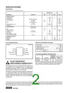
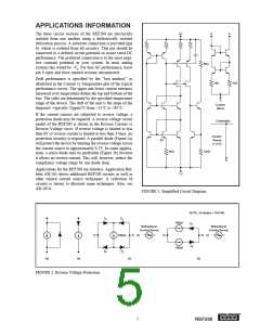
The three circuit sections of the REF200 are electrically
isolated from one another using a dielectrically isolated
fabrication process. A substrate connection is provided (pin
6), which is isolated from all circuitry. This pin should be
connected to a defined circuit potential to assure rated DC
performance. The preferred connection is to the most nega-
tive constant potential in your system. In most analog
systems this would be –VS. For best AC performance, leave
pin 6 open and leave unused sections unconnected.
5kΩ
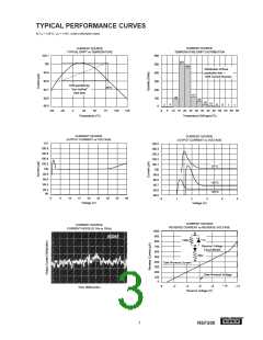
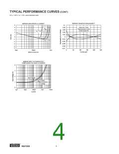
Drift performance is specified by the “box method,” as
illustrated in the Current vs Temperature plot of the typical
performance curves. The upper and lower current extremes
measured over temperature define the top and bottom of the
box. The sides are determined by the specified temperature
range of the device. The drift of the unit is the slope of the
diagonal—typically 25ppm/°C from –25°C to +85°C.
1kΩ
1kΩ
3
Current
Mirror
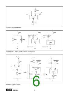
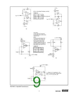
If the current sources are subjected to reverse voltage, a
protection diode may be required. A reverse voltage circuit
model of the REF200 is shown in the Reverse Current vs
Reverse Voltage curve. If reverse voltage is limited to less
than 6V or reverse current is limited to less than 350µA, no
protection circuitry is required. A parallel diode (Figure 2a)
will protect the device by limiting the reverse voltage across
the current source to approximately 0.7V. In some applica-
tions, a series diode may be preferable (Figure 2b) because
it allows no reverse current. This will, however, reduce the
compliance voltage range by one diode drop.
(Substrate)
Current
Source
(1 of 2)
8X
4kΩ
12kΩ
6
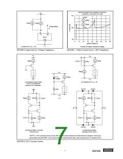
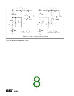
Applications for the REF200 are limitless. Application Bul-
letin AB-165 shows additional REF200 circuits as well as
other related current source techniques. A collection of
circuits is shown to illustrate some techniques. Also, see
AB-165A.
1,2
FIGURE 1. Simplified Circuit Diagram.
NOTE: All diodes = 1N4148.
D1
D1
D3
100µA
100µA
Bidirectional
Current Source
Bidirectional
Current Source
100µA
D2
D2
D
4
(a)
(b)
(c)
(d)
FIGURE 2. Reverse Voltage Protection.
®
5
REF200

 BB [ BURR-BROWN CORPORATION ]