SPECIFICATIONS
ELECTRICAL
At TA = +25°C, VS = 15V, unless otherwise noted.
REF200AP, AU
TYP
PARAMETER
CONDITION
MIN
MAX
UNITS
CURRENT SOURCES
Current Accuracy
Current Match
±0.25
±0.25
±1
±1
%
%
Temperature Drift
Output Impedance
Specified Temp Range
2.5V to 40V
25
100
ppm/°C
MΩ
20
3.5V to 30V
200
500
MΩ
Noise
BW = 0.1Hz to 10Hz
f = 10kHz
1
nAp-p
pA/√Hz
20
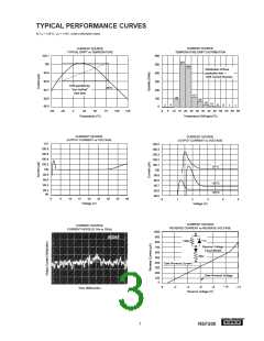
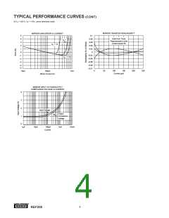
See Curves
10
Voltage Compliance (1%)
Capacitance
TMIN to TMAX
pF
CURRENT MIRROR
I = 100µA Unless
Otherwise Noted
Gain
0.995
40
1
25
100
1.005
Temperature Drift
Impedance (output)
Nonlinearity
ppm/°C
MΩ
%
2V to 40V
I = 0µA to 250µA
0.05
Input Voltage
1.4
V
Output Compliance Voltage
Frequency Response (–3dB)
See Curves
5
Transfer
MHz
TEMPERATURE RANGE
Specification
Operating
–25
–40
–40
+85
+85
+125
°C
°C
°C
Storage
ABSOLUTE MAXIMUM RATINGS
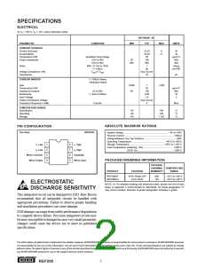
PIN CONFIGURATION
Top View
DIP/SOIC
Applied Voltage ..................................................................... –6V to +40V
Reverse Current ........................................................................... –350µA
Voltage Between Any Two Sections................................................. ±80V
Operating Temperature ................................................... –40°C to +85°C
Storage Temperature .....................................................–40°C to +125°C
Lead Temperature (soldering, 10s) .............................................. +300°C
(SOIC 3s)........................................................+260°C
I1 Low
I2 Low
1
2
3
4
8
7
6
5
I1 High
I2 High
Mirror Common
Mirror Output
Substrate
PACKAGE/ORDERING INFORMATION
Mirror Input
PACKAGE
DRAWING TEMPERATURE
PRODUCT
PACKAGE
NUMBER(1)
RANGE
REF200AP
REF200AU
8-Pin Plastic DIP
8-Pin SOIC
006
182
–25°C to +85°C
–25°C to +85°C
ELECTROSTATIC
DISCHARGE SENSITIVITY
NOTE: (1) For detailed drawing and dimension table, please see end of data
sheet, or Appendix C of Burr-Brown IC Data Book. (2) Grade designation “A”
may not be marked. Absence of grade designation indicates A grade.
This integrated circuit can be damaged by ESD. Burr-Brown
recommends that all integrated circuits be handled with
appropriate precautions. Failure to observe proper handling
and installation procedures can cause damage.
ESD damage can range from subtle performance degradation
to complete device failure. Precision integrated circuits may
be more susceptible to damage because very small parametric
changes could cause the device not to meet its published
specifications.
The information provided herein is believed to be reliable; however, BURR-BROWN assumes no responsibility for inaccuracies or omissions. BURR-BROWN assumes
no responsibility for the use of this information, and all use of such information shall be entirely at the user’s own risk. Prices and specifications are subject to change
without notice. No patent rights or licenses to any of the circuits described herein are implied or granted to any third party. BURR-BROWN does not authorize or warrant
any BURR-BROWN product for use in life support devices and/or systems.
®
2
REF200

 BB [ BURR-BROWN CORPORATION ]