for both if no immediate improvement were noted). This
procedure would require the generation of the digital bit-2
major carry code to the input of the PCM63P and a DVM or
oscilloscope capable of reading the output voltage for a one
LSB step (5.72µV) in addition to a distortion analyzer.
the correct starting direction would be arbitrary. This proce-
dure still requires a good DVM in addition to a distortion
analyzer.
Each user will have to determine if a small improvement in
full-scale THD+N for their application is worth the expense
of performing a proper MSB adjustment.
A more practical approach would be to forego the minor
correction for the bit-2 major carry adjustment and only
adjust for upper and lower DAC gain matching. The prob-
lem is that just by connecting the MSB circuitry to the
PCM63P, the odds are that the upper and lower bit-2 weights
would be greatly changed from their unadjusted states and
thereby adversely affect the desired gain adjustment. Just
centering the 100kΩ potentiometers would not necessarily
provide the correct starting point. To guarantee that each
100kΩ potentiometer would be set to the correct starting or
null point (no current into or out of the MSB adjust pins), the
voltage drop across each corresponding 330kΩ resistor would
have to measure 0V. A voltage drop of ±1.25mV across
either 330kΩ resistor would correspond to a ±1LSB change
in the null point from its unadjusted state (1LSB in current
or 3.81nA x 330kΩ = 1.26mV). Once these starting points
for each potentiometer had been set, each potentiometer
would then be adjusted equally, in opposite directions, to
achieve the lowest full-scale THD+N possible. If no imme-
diate improvement were noted, the direction of rotation for
both potentiometers would be reversed. One direction of
potentiometer counter-rotations would only make the gain
mismatch and resulting THD+N worse, while the opposite
would gradually improve and then worsen the THD+N after
passing through a no mismatch point. The determination of
APPLICATIONS
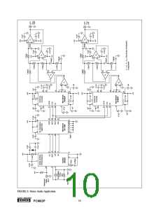
The most common application for the PCM63P is in high-
performance and professional digital audio playback, such
as in CD and DAT players. The circuit in Figure 6 shows the
PCM63P in a typical combination with a digital interface
format receiver chip (Yamaha YM3623), an 8x interpolating
digital filter (Burr-Brown DF1700P), and two third-order
low-pass anti-imaging filters (implemented using Burr-Brown
OPA2604APs).
Using an 8x digital filter increases the number of samples to
the DAC by a factor of 8, thereby reducing the need for a
higher order reconstruction or anti-imaging analog filter on
the DAC output. An analog filter can now be constructed
using a simple phase-linear GIC (generalized immittance
converter) architecture. Excellent sonic performance is
achieved using a digital filter in the design, while reducing
overall circuit complexity at the same time.
Because of its superior low-level performance, the PCM63P
is also ideally suited for other high-performance applications
such as direct digital synthesis (DDS).
®
9
PCM63P

 BB [ BURR-BROWN CORPORATION ]