Copper leadframe construction used in the OPA2604 im-
proves heat dissipation compared to conventional plastic
packages. To achieve best heat dissipation, solder the device
directly to the circuit board and use wide circuit board traces.
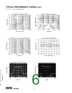
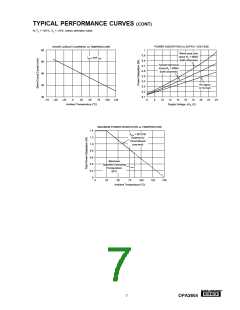
POWER DISSIPATION
The OPA2604 is capable of driving 600Ω loads with power
supply voltages up to ±24V. Internal power dissipation is
increased when operating at high power supply voltage. The
typical performance curve, Power Dissipation vs Power Sup-
ply Voltage, shows quiescent dissipation (no signal or no
load) as well as dissipation with a worst case continuous sine
wave. Continuous high-level music signals typically produce
dissipation significantly less than worst case sine waves.
OUTPUT CURRENT LIMIT
Output current is limited by internal circuitry to approxi-
mately ±40mA at 25°C. The limit current decreases with
increasing temperature as shown in the typical curves.
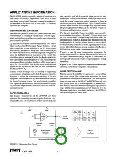
R4
22kΩ
C3
100pF
R1
R2
R3
VIN
1
2
VO
2.7kΩ
22kΩ
10kΩ
OPA2604
C1
3000pF
C2
2000pF
fp = 20kHz
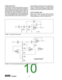
FIGURE 3. Three-Pole Low-Pass Filter.
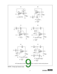
1
2
R1
R5
VO
OPA2604
VIN
6.04kΩ
2kΩ
R2
C3
1000pF
4.02kΩ
R2
Low-pass
3-pole Butterworth
f–3dB = 40kHz
1
4.02kΩ
2
OPA2604
1
2
OPA2604
C1
1000pF
R4
5.36kΩ
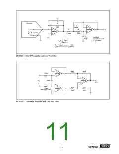
See Application Bulletin AB-026
for information on GIC filters.
C2
1000pF
FIGURE 4. Three-Pole Generalized Immittance Converter (GIC) Low-Pass Filter.
®
OPA2604
10

 BB [ BURR-BROWN CORPORATION ]