If synchronized devices are used, it should be noted that, at
start up, all devices will draw maximum current simulta-
neously. This can cause the input voltage to dip and should
it dip below the minimum input voltage (4.5V), the devices
may not start up. A 2.2µF capacitor should be connected
close to the input pins.
FUNCTIONAL DESCRIPTION
OVERVIEW
The DCP01B offers up to 1W of unregulated output power
with a typical efficiency of up to 85%. This is achieved
through highly integrated packaging technology and the
implementation of a custom power stage and control IC. The
circuit design utilizes an advanced BiCMOS/DMOS pro-
cess.
If more than eight devices are to be synchronized, it is
recommended that the SYNCIN pins are driven by an exter-
nal device. Details are contained in a separate applications
bulletin (AB-153).
POWER STAGE
CONSTRUCTION
This uses a push-pull, center-tapped topology switching at
400kHz (divide by 2 from 800kHz oscillator).
The DCP01B’s basic construction is the same as standard
ICs. There is no substrate within the molded package. The
DCP01B is constructed using an IC, rectifier diodes, and a
wound magnetic toroid on a leadframe. As there is no solder
within the package, the DCP01B does not require any
special PCB assembly processing. This results in an isolated
DC/DC converter with inherently high reliability.
OSCILLATOR AND WATCHDOG
The onboard 800kHz oscillator generates the switching
frequency via a divide by 2 circuit. The oscillator can be
synchronized to other DCP01B circuits or an external source,
and is used to minimize system noise.
A watchdog circuit checks the operation of the oscillator
circuit. The oscillator can be stopped by pulling the SYNC
pin LOW. The output pins will be tri-stated. This will occur
in 2µs.
ADDITIONAL FUNCTIONS
DISABLE/ENABLE
The DCP01B can be disabled or enabled by driving the SYNC
pin using an open drain CMOS gate. If the SYNCIN pin is
pulled low, the DCP01B will be disabled. The disable time
depends upon the external loading; the internal disable func-
tion is implemented in 2µs. Removal of the pull down will
cause the DCP01B to be enabled.
THERMAL SHUTDOWN
The DCP01B is protected by a thermal shutdown circuit. If
the on-chip temperature exceeds 150°C, the device will shut
down. Once the temperature falls below 150°C, normal
operation will resume.
Capacitive loading on the SYNCIN pin should be minimized
in order to prevent a reduction in the oscillator frequency.
SYNCHRONIZATION
DECOUPLING
In the event that more than one DC/DC converter is needed
onboard, beat frequencies and other electrical interference
can be generated. This is due to the small variations in
switching frequencies between the DC/DC converters.
Ripple Reduction
The high switching frequency of 400kHz allows simple
filtering. To reduce ripple, it is recommended that at least a
1µF capacitor is used on VOUT. Dual outputs should both be
decoupled to pin 5. A 2.2µF low ESR capacitor on the input
of the 5V in versions, and a 0.47µF low ESR cap on the 24V
DCP01B in versions is recommended.
The DCP01B overcomes this by allowing devices to be
synchronized to one another. Up to eight devices can be
synchronized by connecting the SYNCIN pins together, tak-
ing care to minimize the capacitance of tracking. Stray
capacitance (> 3pF) will have the effect of reducing the
switching frequency, or even stopping the oscillator circuit.
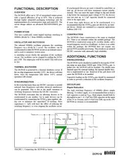
VSUPPLY
VOUT 1
VS
SYNCIN
0V
DCP
01B
0V
VOUT1 + VOUT 2
VS
VOUT 2
DCP
01B
SYNCIN
0V
0V
COM
FIGURE 1. Connecting the DCP01B in Series.
®
7
DCP01B

 BB [ BURR-BROWN CORPORATION ]