The DCP01B is a switching power supply and as such can
place high peak current demands on the input supply. In
order to avoid the supply falling momentarily during the fast
switching pulses ground and power planes should be used to
track the power to the input of DCP01B. If this is not
possible then the supplies must be connected in a star
formation with the tracks made as wide as possible.
Connecting the DCP01B in Series
Multiple DCP01B isolated 1W DC/DC converters can be
connected in series to provide nonstandard voltage rails.
This is possible by utilizing the floating outputs provided by
the DCP01B’s galvanic isolation.
Connect the positive VOUT from one DCP01B to the nega-
tive VOUT (0V) of another (see Figure 1). If the SYNCIN pins
are tied together, the self-synchronization feature of the
DCP01B will prevent beat frequencies on the voltage rails.
The SYNCIN feature of the DCP01B allows easy series
connection without external filtering, minimizing cost.
If the SYNCIN pin is being used then the tracking between
device SYNCIN pins should be short to avoid stray capaci-
tance. If the SYNCIN pin is not being used it is advisable to
place a guard ring, (connected to input ground) around this
pin to avoid any noise pick up.
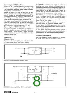
The outputs on dual output DCP01B versions can also be
connected in series to provide two times the magnitude of
VOUT as shown in Figure 2. For example, a dual 15V
DCP01B could be connected to provide a 30V rail.
The output should be taken from the device using ground
and power planes, this will ensure minimum losses.
A good quality low ESR capacitor placed as close as
practicable across the input will reduce reflected ripple and
ensure a smooth start up.
Connecting the DCP01B in Parallel
If the output power from one DCP01B is not sufficient, it is
possible to parallel the outputs of multiple DCP01Bs, as
shown in Figure 3. Again, the SYNCIN feature allows easy
synchronization to prevent power-rail beat frequencies at no
additional filtering cost.
A good quality low ESR capacitor placed as close as
practicable across the rectifier output terminal and output
ground will give the best ripple and noise performance.
THERMAL MANAGEMENT
Due to the high power density of this device it is advisable
to provide ground planes on the input and output.
PCB LAYOUT
Ripple and Noise
Careful consideration should be given to the layout of the
PCB in order that the best results can be obtained.
VSUPPLY
+VOUT
VS
+VOUT
–VOUT
0V
DCP
01B
–VOUT
0V
COM
FIGURE 2. Connecting Dual Outputs in Series.
VSUPPLY
VOUT
VS
SYNCIN
DCP
DCP
01B
01B
0V
0V
VS
2 x Power Out
VOUT
SYNCIN
0V
0V
COM
FIGURE 3. Connecting Multiple DCP01Bs in Parallel.
®
8
DCP01B

 BB [ BURR-BROWN CORPORATION ]