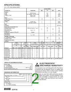
SPECIFICATIONS
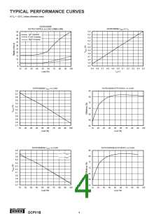
At TA = +25°C, unless otherwise specified.
DCP01B SERIES
TYP
PARAMETER
CONDITIONS
MIN
MAX
UNITS
OUTPUT
Power
Ripple
100% Full Load
O/P Capacitor = 1µF, 50% Load
Room to Cold
0.97
20
0.046
0.016
W
mVp-p
%/°C
%/°C
Voltage vs Temp
Room to Hot
INPUT
Voltage Range on VS
–10
10
%
ISOLATION
Voltage
1s Flash Test
60s Test, UL1950(1)
1
1
kVrms
kVrms
LINE
Regulation
1
%/1% of VS
SWITCHING/SYNCHRONIZATION
Oscillator Frequency (fOSC
Sync Input Low
Sync Input Current
Disable Time
Capacitance Loading on SYNCIN Pin
)
Switching Frequency = fOSC/2
VSYNC = +2V
800
kHz
V
µA
µs
pF
0
0.4
75
2
External
3
RELIABILITY
Demonstrated
TA = +55°C
75
FITS
THERMAL SHUTDOWN
IC Temperature at Shutdown
Shutdown Current
150
3
°C
mA
TEMPERATURE RANGE
Operating
–40
+100
°C
INPUT
OUTPUT
LOAD
NO LOAD
BARRIER
VOLTAGE (V)
VOLTAGE (V)
REGULATION (%)
CURRENT (mA)
EFFICIENCY (%) CAPACITANCE (pF)
VS
VNOM
IQ
CISO
75% LOAD(2)
10% TO 100% LOAD(3)
0% LOAD
100% LOAD
TYP
VISO = 750VRMS
TYP
PRODUCT
MIN
TYP
MAX
MIN
TYP
MAX
TYP
MAX
TYP
DCP010505B
DCP010505DB
DCP010512B
DCP010512DB
DCP010515B
DCP010515DB
DCP012405B
4.5
4.5
4.5
4.5
4.5
4.5
21.6
5
5
5.5
5.5
5.5
5.5
5.5
5.5
26.4
4.75
±4.25
11.4
5
5.25
±5.75
12.6
19
18
21
19
26
19
13
31
32
38
37
42
41
23
20
22
29
40
34
42
14
80
81
85
82
82
85
77
3.6
3.8
5.1
4.0
3.8
4.7
3.8
±5
5
12
±12
15
5
±11.4
14.25
±14.25
4.75
±12.6
15.75
5
5
±15 ±15.75
5.25
24
5
NOTES: (1) During UL1950 recognition tests only. (2) 100% Load Current = 1W/VNOM TYP. (3) Load regulation = (VOUT at 10% Load – VOUT at 100% Load)/VOUT
at 75% Load.
ABSOLUTE MAXIMUM RATINGS
ELECTROSTATIC
DISCHARGE SENSITIVITY
This integrated circuit can be damaged by ESD. Burr-Brown
recommends that all integrated circuits be handled with
Input Voltage:
5V Input Models .................................................................................. 7V
24V Input Models .............................................................................. 29V
Storage Temperature ...................................................... –60°C to +125°C
Lead Temperature (soldering, 10s) ................................................. 270°C
appropriate precautions. Failure to observe proper handling
and installation procedures can cause damage.
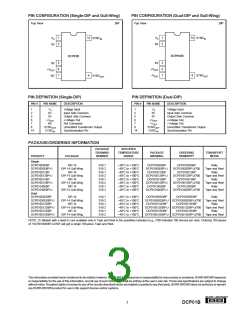
ORDERING INFORMATION
ESD damage can range from subtle performance degrada-
tion to complete device failure. Precision integrated circuits
may be more susceptible to damage because very small
parametric changes could cause the device not to meet its
published specifications.
(
( B )
)
(D )
DCP01 05 05
Basic Model Number: 1W Product
Voltage Input:
5V In
Voltage Output:
5V Out
Dual Output:
Model Revision:
Package Code:
P = PDIP-14
P-U = PDIP-14 Gull-Wing
®
2
DCP01B

 BB [ BURR-BROWN CORPORATION ]