WORLD-BEAM QS18U Ultrasonic Sensors
Temperature Effects
The speed of sound is dependent upon the composition, pressure and temperature of the gas in which it is traveling. For
most ultrasonic applications, the composition and pressure of the gas are relatively fixed, while the temperature may
fluctuate.
In air, the speed of sound varies with temperature according to the following approximation:
In metric
units:
In English units:
C
=
√
=
C
ft/s
√
49 460 + T
F
20 273 + T
m/s
C
Cm/s = speed of sound in meters per second
TC = temperature in °C
Cft/s = speed of sound in feet per second
TF = temperature in °F
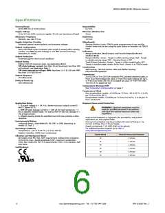
Temperature Compensation
Changes in air temperature affect the speed of sound, which in turn affects the distance reading measured by the sensor.
An increase in air temperature shifts both sensing window limits closer to the sensor. Conversely, a decrease in air
temperature shifts both limits farther away from the sensor. This shift is approximately 3.5% of the limit distance for a 20°
C change in temperature.
The QS18U series ultrasonic sensors are temperature compensated This reduces the error due to temperature by about
90%. The sensor will maintain its window limits to within 1.8% over the -20° to +60° C (−4° to +140° F) range.
NOTE:
•
•
•
Exposure to direct sunlight can affect the sensor’s ability to accurately compensate for changes
in temperature.
If the sensor is measuring across a temperature gradient, the compensation will be less
effective.
The temperature warmup drift upon power-up is less than 7% of the sensing distance. After 5
minutes, the apparent switchpoint will be within 0.6% of the actual position. After 25 minutes,
the sensing position will be stable.
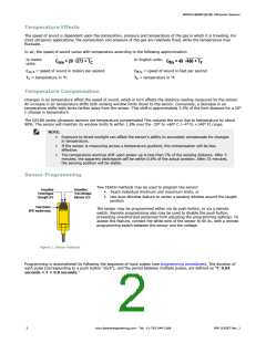
Sensor Programming
Two TEACH methods may be used to program the sensor:
Green/Red
Power/Signal
Strength LED
Yellow/Red
TEACH/Output
Indicator LED
•
•
Teach individual minimum and maximum limits, or
Use Auto-Window feature to center a sensing window around the taught
position
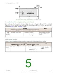
Push Button
(IP67 models only)
The sensor may be programmed either via its push button, or via a remote
switch. Remote programming also may be used to disable the push button,
preventing unauthorized personnel from adjusting the programming settings. To
access this feature, connect the white wire of the sensor to 0V dc, with a remote
programming switch between the sensor and the voltage.
Figure 1. Sensor Features
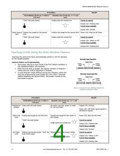
Programming is accomplished by following the sequence of input pulses (see programming procedures). The duration of
each pulse (corresponding to a push button “click”), and the period between multiple pulses, are defined as “T: 0.04
seconds < T < 0.8 seconds."
2
www.bannerengineering.com - Tel: +1-763-544-3164
P/N 119287 Rev. J

 BANNER [ Banner Engineering ]