AllꢀAvagoꢀdataꢀsheetsꢀreportꢀtheꢀcreepageꢀandꢀclearanceꢀ theꢀsurfaceꢀofꢀaꢀprintedꢀcircuitꢀboardꢀbetweenꢀtheꢀsolderꢀ
inherentꢀ toꢀ theꢀ optocouplerꢀ componentꢀ itself.ꢀ Theseꢀ filletsꢀofꢀtheꢀinputꢀandꢀoutputꢀleadsꢀmustꢀbeꢀconsidered.ꢀ
dimensionsꢀ areꢀ neededꢀ asꢀ aꢀ startingꢀ pointꢀ forꢀ theꢀ Thereꢀ areꢀ recommendedꢀ techniquesꢀ suchꢀ asꢀ groovesꢀ
equipmentꢀdesignerꢀwhenꢀdeterminingꢀtheꢀcircuitꢀinsula- andꢀribsꢀwhichꢀmayꢀbeꢀusedꢀonꢀaꢀprintedꢀcircuitꢀboardꢀ
tionꢀrequirements.ꢀHowever,ꢀonceꢀmountedꢀonꢀaꢀprintedꢀ toꢀachieveꢀdesiredꢀcreepageꢀandꢀclearances.ꢀCreepageꢀ
circuitꢀboard,ꢀminimumꢀcreep-ageꢀandꢀclearanceꢀrequire- andꢀclearanceꢀdistancesꢀwillꢀalsoꢀchangeꢀdependingꢀonꢀ
mentsꢀmustꢀbeꢀmetꢀasꢀspecifiedꢀforꢀindividualꢀequipmentꢀ factorsꢀsuchꢀasꢀpollutionꢀdegreeꢀandꢀinsulationꢀlevel.
standards.ꢀForꢀcreepage,ꢀtheꢀshortestꢀdistanceꢀpathꢀalongꢀ
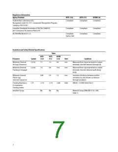
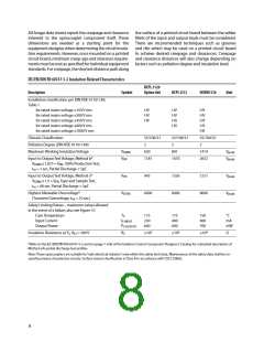
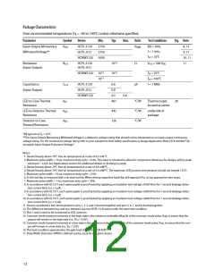
IEC/EN/DIN EN 60747-5-2 Insulation Related Characteristics
HCPL-3120
Description
Symbol
Option 060
HCPL-J312
HCNW3120
Unit
InstallationꢀclassificationꢀperꢀDINꢀVDEꢀ0110/1.89,ꢀ
Tableꢀ1ꢀ
ꢀ
ꢀ
ꢀ
ꢀ
ꢀ
ꢀ
ꢀ
ꢀ
ꢀ
ꢀ ꢀ
ꢀ
ꢀ
ꢀ
ꢀ
ꢀ
ꢀ
ꢀ
ꢀ
ꢀ
ꢀ
forꢀratedꢀmainsꢀvoltageꢀ≤150ꢀVꢀrmsꢀ
forꢀratedꢀmainsꢀvoltageꢀ≤300ꢀVꢀrmsꢀ
forꢀratedꢀmainsꢀvoltageꢀ≤450ꢀVꢀrmsꢀ
forꢀratedꢀmainsꢀvoltageꢀ≤600ꢀVꢀrmsꢀ
forꢀratedꢀmainsꢀvoltageꢀ≤1000ꢀVꢀrmsꢀ
I-IVꢀ
I-IVꢀ
I-IIIꢀ
ꢀ
I-IVꢀ
I-IVꢀ
I-IIIꢀ
I-IIIꢀ
ꢀ
I-IVꢀ
I-IVꢀ
I-IVꢀ
I-IVꢀ
I-III
ꢀ
ClimaticꢀClassificationꢀ
ꢀ
ꢀ
55/100/21ꢀ
2ꢀ
55/100/21ꢀ
2ꢀ
55/100/21
2
PollutionꢀDegreeꢀ(DINꢀVDEꢀ0110/1.89)ꢀ
MaximumꢀWorkingꢀInsulationꢀVoltageꢀ
InputꢀtoꢀOutputꢀTestꢀVoltage,ꢀMethodꢀb*ꢀ
VIORM
ꢀ
630ꢀ
891ꢀ
1414ꢀ
2652ꢀ
Vpeak
Vpeak
VPR
ꢀ
1181ꢀ
1670ꢀ
ꢀ
ꢀ
ꢀ
ꢀ
ꢀ
VIORMꢀxꢀ1.875ꢀ=ꢀVPR,ꢀ100%ꢀProductionꢀTest,ꢀ
tmꢀ=ꢀ1ꢀsec,ꢀPartialꢀDischargeꢀ<ꢀ5pCꢀ
ꢀ
ꢀ
ꢀ
ꢀ
ꢀ
InputꢀtoꢀOutputꢀTestꢀVoltage,ꢀMethodꢀa*ꢀ
VPR
ꢀ
945ꢀ
1336ꢀ
2121ꢀ
Vpeak
ꢀ
ꢀ
VIORMꢀxꢀ1.5ꢀ=ꢀVPR,ꢀTypeꢀandꢀSampleꢀTest,ꢀ
tmꢀ=ꢀ60ꢀsec,ꢀPartialꢀDischargeꢀ<ꢀ5pC
HighestꢀAllowableꢀOvervoltage*ꢀ
(TransientꢀOvervoltage,ꢀtiniꢀ=ꢀ10ꢀsec)ꢀ
VIOTM
ꢀ
ꢀ
6000ꢀ
ꢀ
6000ꢀ
ꢀ
8000ꢀ
ꢀ
Vpeak
ꢀ
ꢀ
SafetyꢀLimitingꢀValuesꢀ–ꢀmaximumꢀvaluesꢀallowedꢀ
inꢀtheꢀeventꢀofꢀaꢀfailure,ꢀalsoꢀseeꢀFigureꢀ37.ꢀ
ꢀ
ꢀ
ꢀ
ꢀ
ꢀ ꢀ
ꢀ
ꢀ
ꢀ
ꢀꢀꢀꢀCaseꢀTemperatureꢀ
ꢀꢀꢀꢀInputꢀCurrentꢀ
ꢀꢀꢀꢀOutputꢀPowerꢀ
TSꢀ
175ꢀ
230ꢀ
600ꢀ
175ꢀ
400ꢀ
600ꢀ
150ꢀ
400ꢀ
700ꢀ
°Cꢀ
mAꢀ
mW
ISꢀINPUT
PSꢀOUTPUT
RSꢀ
ꢀ
ꢀ
InsulationꢀResistanceꢀatꢀTS,ꢀVIOꢀ=ꢀ500ꢀVꢀ
≥109ꢀ
≥109ꢀ
≥109ꢀ
Ω
*ReferꢀtoꢀtheꢀIEC/EN/DINꢀENꢀ60747-5-2ꢀsectionꢀ(pageꢀ1-6/8)ꢀofꢀtheꢀIsolationꢀControlꢀComponentꢀDesigner’sꢀCatalogꢀforꢀaꢀdetailedꢀdescriptionꢀofꢀ
Methodꢀa/bꢀpartialꢀdischargeꢀtestꢀprofiles.
Note:ꢀTheseꢀoptocouplersꢀareꢀsuitableꢀforꢀ“safeꢀelectricalꢀisolation”ꢀonlyꢀwithinꢀtheꢀsafetyꢀlimitꢀdata.ꢀMaintenanceꢀofꢀtheꢀsafetyꢀdataꢀshallꢀbeꢀen-
suredꢀbyꢀmeansꢀofꢀprotectiveꢀcircuits.ꢀSurfaceꢀmountꢀclassificationꢀisꢀClassꢀAꢀinꢀaccordanceꢀwithꢀCECCꢀ00802.
8

 AVAGO [ AVAGO TECHNOLOGIES LIMITED ]