S494P
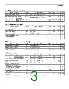
Dead Time Control Section
Characteristic
Symbol
IIB(DT)
Test Condition
Vcc = 15V, 0V < V4 < 5.25V
Min. Typ. Max. Unit
㎂
Input Bias Current (Pin4)
-
-2
-10
Vcc = 15V, Pin4 = 0V,
Output Control Pin = Vref
Max. Duty cycle, Each Output
DC(Max)
43
-
45
%
Zero Duty
Max Duty
-
3
-
3.3
-
Input Threshold
Voltage
VTH
-
V
0
Error Amplifier Section
Characteristic
Input Offset Voltage
Input Offset Current
Input Bias Current
Symbol
VIOS
Test Condition
V3 = 2.5V
Min. Typ. Max. Unit
-
-
-
2
10
250
1
mV
nA
㎂
IIOS
V3 = 2.5V
25
0.2
IIB
V3 = 2.5V
Input Common Mode
voltage Range
VICR
7V ≤ VCC ≤ 40V
-0.3
-
VCC
V
Large Signal Open Loop
Voltage Range
GVO
fC
0.5V ≤ V3 ≤ 3.5V
60
-
74
-
-
dB
㎑
Unity Gain Band width
-
650
PWM Comparator Section (Pin3)
Characteristic
Inhibit Threshold Voltage
Output Source Current
Output Sink Current
Symbol
VTHI
Test Condition
Zero duty cycle
Min. Typ. Max. Unit
-
4
4.5
V
Io+
Io-
0.5V < V3 < 3.5V
0.5V< V3 < 3.5V
2
-
-
-
mA
mA
-0.2
-0.6
Output Section
Characteristic
Symbol
Test Condition
VE= 15V, IC = 200mA
VC =15V, IE = 200mA
VCC = VC = 40V, VE = 0
VCC = VC = 40V, VE = 0
Min. Typ. Max. Unit
Common-Emitter
-
-
-
-
1.1
1.5
2
1.3
Output Satur-
ation Voltage
VCE(SAT)
V
Emitter-Follower
2.5
Collector off-state Current
Emitter off-state Current
Output Control(Pin 13)
IC(off)
IE(off)
100
-100
㎂
-
Output Control Voltage
Required for single-Ended or
Parallel Output Operation
Output Control Voltage Req-
uired for Push-pull operation
VOCL
VOCH
-
-
-
-
-
0.4
-
V
V
2.4
Total Device
Standby power Supply
Current
ICC
-
-
6
10
mA
: These limits apply when the voltage measured at Pin 3 is with in the range specified.
KSI-L010-000
3

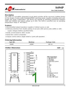
 AUK [ AUK CORP ]