Power-down Mode
When the SM1..0 bits are written to 01 or 11, the SLEEP instruction makes the MCU
enter Power-down mode. In this mode, the external Oscillator is stopped, while the
external interrupts, the USI start condition detection, and the Watchdog continue operat-
ing (if enabled). Only an External Reset, a Watchdog Reset, a Brown-out Reset, USI
start condition interrupt, an external level interrupt on INT0, or a pin change interrupt can
wake up the MCU. This sleep mode basically halts all generated clocks, allowing opera-
tion of asynchronous modules only.
Note that if a level triggered interrupt is used for wake-up from Power-down mode, the
changed level must be held for some time to wake up the MCU. Refer to “External Inter-
rupts” on page 58 for details.
When waking up from Power-down mode, there is a delay from the wake-up condition
occurs until the wake-up becomes effective. This allows the clock to restart and become
stable after having been stopped. The wake-up period is defined by the same CKSEL
Fuses that define the Reset Time-out period, as described in “Clock Sources” on page
22.
Standby Mode
When the SM1..0 bits are 10 and an external crystal/resonator clock option is selected,
the SLEEP instruction makes the MCU enter Standby mode. This mode is identical to
Power-down with the exception that the Oscillator is kept running. From Standby mode,
the device wakes up in six clock cycles.
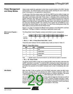
Table 14. Active Clock Domains and Wake-up Sources in the Different Sleep Modes.
Active Clock Domains
Oscillators
Wake-up Sources
Sleep Mode
Idle
X
X
X
X
X
X
X
X
X
Power-down
Standby(1)
X(2)
X(2)
Notes: 1. Only recommended with external crystal or resonator selected as clock source.
2. For INT0, only level interrupt.
Minimizing Power
Consumption
There are several issues to consider when trying to minimize the power consumption in
an AVR controlled system. In general, sleep modes should be used as much as possi-
ble, and the sleep mode should be selected so that as few as possible of the device’s
functions are operating. All functions not needed should be disabled. In particular, the
following modules may need special consideration when trying to achieve the lowest
possible power consumption.
Analog Comparator
When entering Idle mode, the Analog Comparator should be disabled if not used. In
other sleep modes, the Analog Comparator is automatically disabled. However, if the
Analog Comparator is set up to use the Internal Voltage Reference as input, the Analog
Comparator should be disabled in all sleep modes. Otherwise, the Internal Voltage Ref-
erence will be enabled, independent of sleep mode. Refer to “Analog Comparator” on
page 148 for details on how to configure the Analog Comparator.
30
ATtiny2313/V
2543F–AVR–08/04

 ATMEL [ ATMEL ]