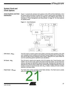
Clock Sources
The device has the following clock source options, selectable by Flash Fuse bits as
shown below. The clock from the selected source is input to the AVR clock generator,
and routed to the appropriate modules.
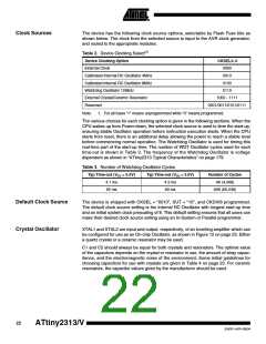
Table 2. Device Clocking Select(1)
Device Clocking Option
External Clock
CKSEL3..0
0000
Calibrated Internal RC Oscillator 4MHz
Calibrated internal RC Oscillator 8MHz
Watchdog Oscillator 128kHz
External Crystal/Ceramic Resonator
Reserved
0010
0100
0110
1000 - 1111
0001/0011/0101/0111
Note:
1. For all fuses “1” means unprogrammed while “0” means programmed.
The various choices for each clocking option is given in the following sections. When the
CPU wakes up from Power-down, the selected clock source is used to time the start-up,
ensuring stable Oscillator operation before instruction execution starts. When the CPU
starts from reset, there is an additional delay allowing the power to reach a stable level
before commencing normal operation. The Watchdog Oscillator is used for timing this
real-time part of the start-up time. The number of WDT Oscillator cycles used for each
time-out is shown in Table 3. The frequency of the Watchdog Oscillator is voltage
dependent as shown in “ATtiny2313 Typical Characteristics” on page 179.
Table 3. Number of Watchdog Oscillator Cycles
Typ Time-out (VCC = 5.0V)
Typ Time-out (VCC = 3.0V)
Number of Cycles
4K (4,096)
4.1 ms
65 ms
4.3 ms
69 ms
64K (65,536)
Default Clock Source
Crystal Oscillator
The device is shipped with CKSEL = “0010”, SUT = “10”, and CKDIV8 programmed.
The default clock source setting is the Internal RC Oscillator with longest start-up time
and an initial system clock prescaling of 8. This default setting ensures that all users can
make their desired clock source setting using an In-System or Parallel programmer.
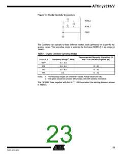
XTAL1 and XTAL2 are input and output, respectively, of an inverting amplifier which can
be configured for use as an On-chip Oscillator, as shown in Figure 12 on page 23. Either
a quartz crystal or a ceramic resonator may be used.
C1 and C2 should always be equal for both crystals and resonators. The optimal value
of the capacitors depends on the crystal or resonator in use, the amount of stray capac-
itance, and the electromagnetic noise of the environment. Some initial guidelines for
choosing capacitors for use with crystals are given in Table 4 on page 23. For ceramic
resonators, the capacitor values given by the manufacturer should be used.
22
ATtiny2313/V
2543F–AVR–08/04

 ATMEL [ ATMEL ]