ATmega64A
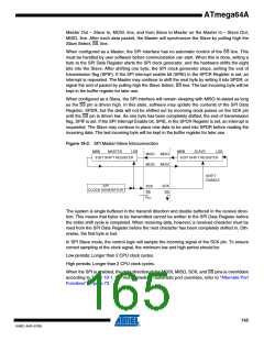
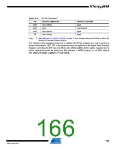
Table 19-1. SPI Pin Overrides(1)
Pin
MOSI
MISO
SCK
SS
Direction, Master SPI
User Defined
Input
Direction, Slave SPI
Input
User Defined
Input
User Defined
User Defined
Input
Note:
1. See “Alternate Functions of Port B” on page 76 for a detailed description of how to define the
direction of the user defined SPI pins.
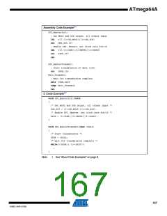
The following code examples show how to initialize the SPI as a Master and how to perform a
simple transmission. DDR_SPI in the examples must be replaced by the actual Data Direction
Register controlling the SPI pins. DD_MOSI, DD_MISO and DD_SCK must be replaced by the
actual data direction bits for these pins. For example, if MOSI is placed on pin PB5, replace
DD_MOSI with DDB5 and DDR_SPI with DDRB.
166
8160C–AVR–07/09

 ATMEL [ ATMEL ]