ATmega16/32/64/M1/C1
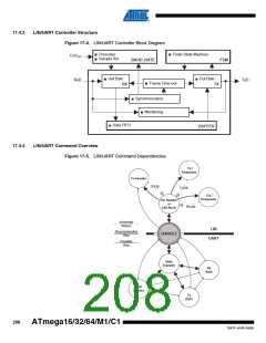
17.4.1
LIN Overview
The LIN/UART controller is designed to match as closely as possible to the LIN software appli-
cation structure. The LIN software application is developed as independent tasks, several slave
tasks and one master task (c.f. Section 17.3.4 on page 206). The ATmega16/32/64/M1/C1 con-
forms to this perspective. The only link between the master task and the slave task will be at the
cross-over point where the interrupt routine is called once a new identifier is available. Thus, in a
master node, housing both master and slave task, the Tx LIN Header function will alert the slave
task of an identifier presence. In the same way, in a slave node, the Rx LIN Header function will
alert the slave task of an identifier presence.
When the slave task is warned of an identifier presence, it has first to analyze it to know what to
do with the response. Hardware flags identify the presence of one of the specific identifiers from
60 (0x3C) up to 63 (0x3F).
For LIN communication, only four interrupts need to be managed:
• LIDOK: New LIN identifier available,
• LRXOK: LIN response received,
• LTXOK: LIN response transmitted,
• LERR: LIN Error(s).
The wake-up management can be automated using the UART wake-up capability and a node
sending a minimum of 5 low bits (0xF0) for LIN 2.1 and 8 low bits (0x80) for LIN 1.3. Pin change
interrupt on LIN wake-up signal can be also used to exit the device of one of its sleep modes.
Extended frame identifiers 62 (0x3E) and 63 (0x3F) are reserved to allow the embedding of
user-defined message formats and future LIN formats. The byte transfer mode offered by the
UART will ensure the upwards compatibility of LIN slaves with accommodation of the LIN
protocol.
17.4.2
UART Overview
The LIN/UART controller can also function as a conventional UART. By default, the UART oper-
ates as a full duplex controller. It has local loop back circuitry for test purposes. The UART has
the ability to buffer one character for transmit and two for receive. The receive buffer is made of
one 8-bit serial register followed by one 8-bit independent buffer register. Automatic flag man-
agement is implemented when the application puts or gets characters, thus reducing the
software overhead. Because transmit and receive services are independent, the user can save
one device pin when one of the two services is not used. The UART has an enhanced baud rate
generator providing a maximum error of 2% whatever the clock frequency and the targeted baud
rate.
207
7647F–AVR–04/09

 ATMEL [ ATMEL ]