14. Power Stage Controller – (PSC) (only ATmega16/32/64M1)
The Power Stage Controller is a high performance waveform controller.
14.1 Features
• PWM waveform generation function with 6 complementary programmable outputs (able to
control 3 half-bridges)
• Programmable dead time control
• PWM up to 12 bit resolution
• PWM clock frequency up to 64 MHz (via PLL)
• Programmable ADC trigger
• Automatic Overlap protection
• Failsafe emergency inputs - 3 (to force all outputs to high impedance or in inactive state - fuse
configurable)
• Center aligned and edge aligned modes synchronization
14.2 Overview
Many register and bit references in this section are written in general form.
• A lower case “n” replaces the PSC module number, in this case 0, 1 or 2. However, when
using the register or bit defines in a program, the precise form must be used, i.e.,
POCR0SAH for accessing module 0 POCRnSAH register and so on.
• A lower case “x” replaces the PSC part , in this case A or B. However, when using the register
or bit defines in a program, the precise form must be used, i.e., OCR0SAH for accessing part
A OCR0SxH register and so on.
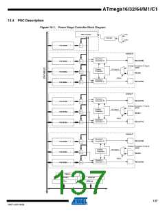
The purpose of the Power Stage Controller (PSC) is to control an external power interface. It has
six outputs to drive for example a 3 half-bridge. This feature allows you to generate three phase
waveforms for applications such as Asynchronous or BLDC motor drives, lighting systems...
The PSC also has 3 inputs, the purpose of which is to provide fast emergency stop capability.
The PSC outputs are programmable as “active high” or “active low”. All the timing diagrams in
the following examples are given in the “active high” polarity.
14.3 Accessing 16-bit Registers
Some PSC registers are 16-bit registers. These registers can be accessed by the AVR CPU via
the 8-bit data bus. The 16-bit registers must be byte accessed using two read or write opera-
tions. The PSC has a single 8-bit register for temporary storing of the high byte of the 16-bit
access. The same temporary register is shared between all PSC 16-bit registers. Accessing the
low byte triggers the 16-bit read or write operation. When the low byte of a 16-bit register is writ-
ten by the CPU, the high byte stored in the temporary register, and the low byte written are both
copied into the 16-bit register in the same clock cycle. When the low byte of a 16-bit register is
read by the CPU, the high byte of the 16-bit register is copied into the temporary register in the
same clock cycle as the low byte is read.
To do a 16-bit write, the high byte must be written before the low byte. For a 16-bit read, the low
byte must be read before the high byte.
136
ATmega16/32/64/M1/C1
7647F–AVR–04/09

 ATMEL [ ATMEL ]