ATmega48/88/168
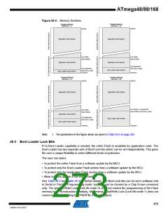
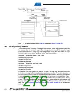
Figure 26-2. Memory Sections
Program Memory
BOOTSZ = '10'
Program Memory
BOOTSZ = '11'
0x0000
0x0000
Application Flash Section
Application Flash Section
End RWW
End RWW
Start NRWW
Start NRWW
Application Flash Section
Boot Loader Flash Section
Application Flash Section
Boot Loader Flash Section
End Application
End Application
Start Boot Loader
Flashend
Start Boot Loader
Flashend
0x0000
Program Memory
BOOTSZ = '01'
Program Memory
BOOTSZ = '00'
0x0000
Application Flash Section
Application Flash Section
End RWW, End Application
End RWW
Start NRWW, Start Boot Loader
Start NRWW
Application Flash Section
Boot Loader Flash Section
End Application
Boot Loader Flash Section
Start Boot Loader
Flashend
Flashend
Note:
1. The parameters in the figure above are given in Table 26-6 on page 282.
26.5 Boot Loader Lock Bits
If no Boot Loader capability is needed, the entire Flash is available for application code. The
Boot Loader has two separate sets of Boot Lock bits which can be set independently. This gives
the user a unique flexibility to select different levels of protection.
The user can select:
• To protect the entire Flash from a software update by the MCU.
• To protect only the Boot Loader Flash section from a software update by the MCU.
• To protect only the Application Flash section from a software update by the MCU.
• Allow software update in the entire Flash.
See Table 26-2 and Table 26-3 for further details. The Boot Lock bits can be set in software and
in Serial or Parallel Programming mode, but they can be cleared by a Chip Erase command
only. The general Write Lock (Lock Bit mode 2) does not control the programming of the Flash
memory by SPM instruction. Similarly, the general Read/Write Lock (Lock Bit mode 1) does not
control reading nor writing by LPM/SPM, if it is attempted.
273
2545M–AVR–09/07

 ATMEL [ ATMEL ]