ATmega48/88/168
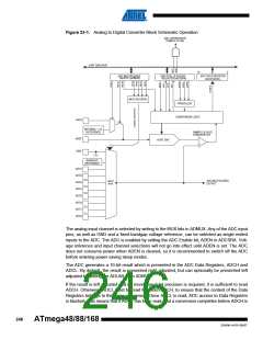
read, neither register is updated and the result from the conversion is lost. When ADCH is read,
ADC access to the ADCH and ADCL Registers is re-enabled.
The ADC has its own interrupt which can be triggered when a conversion completes. When ADC
access to the Data Registers is prohibited between reading of ADCH and ADCL, the interrupt
will trigger even if the result is lost.
23.3 Starting a Conversion
A single conversion is started by disabling the Power Reduction ADC bit, PRADC, in “Minimizing
Power Consumption” on page 42 by writing a logical zero to it and writing a logical one to the
ADC Start Conversion bit, ADSC. This bit stays high as long as the conversion is in progress
and will be cleared by hardware when the conversion is completed. If a different data channel is
selected while a conversion is in progress, the ADC will finish the current conversion before per-
forming the channel change.
Alternatively, a conversion can be triggered automatically by various sources. Auto Triggering is
enabled by setting the ADC Auto Trigger Enable bit, ADATE in ADCSRA. The trigger source is
selected by setting the ADC Trigger Select bits, ADTS in ADCSRB (See description of the ADTS
bits for a list of the trigger sources). When a positive edge occurs on the selected trigger signal,
the ADC prescaler is reset and a conversion is started. This provides a method of starting con-
versions at fixed intervals. If the trigger signal still is set when the conversion completes, a new
conversion will not be started. If another positive edge occurs on the trigger signal during con-
version, the edge will be ignored. Note that an Interrupt Flag will be set even if the specific
interrupt is disabled or the Global Interrupt Enable bit in SREG is cleared. A conversion can thus
be triggered without causing an interrupt. However, the Interrupt Flag must be cleared in order to
trigger a new conversion at the next interrupt event.
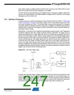
Figure 23-2. ADC Auto Trigger Logic
ADTS[2:0]
PRESCALER
CLKADC
START
ADIF
ADATE
SOURCE 1
.
.
.
.
CONVERSION
LOGIC
EDGE
DETECTOR
SOURCE n
ADSC
Using the ADC Interrupt Flag as a trigger source makes the ADC start a new conversion as soon
as the ongoing conversion has finished. The ADC then operates in Free Running mode, con-
stantly sampling and updating the ADC Data Register. The first conversion must be started by
writing a logical one to the ADSC bit in ADCSRA. In this mode the ADC will perform successive
conversions independently of whether the ADC Interrupt Flag, ADIF is cleared or not.
247
2545M–AVR–09/07

 ATMEL [ ATMEL ]