ATmega8(L)
Clear Timer on
In Clear Timer on Compare or CTC mode (WGM21:0 = 2), the OCR2 Register is used to manip-
Compare Match (CTC) ulate the counter resolution. In CTC mode the counter is cleared to zero when the counter value
Mode
(TCNT2) matches the OCR2. The OCR2 defines the top value for the counter, hence also its
resolution. This mode allows greater control of the Compare Match output frequency. It also sim-
plifies the operation of counting external events.
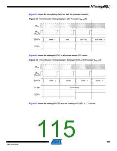
The timing diagram for the CTC mode is shown in Figure 49. The counter value (TCNT2)
increases until a Compare Match occurs between TCNT2 and OCR2, and then counter (TCNT2)
is cleared.
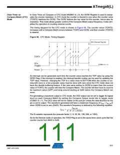
Figure 49. CTC Mode, Timing Diagram
OCn Interrupt Flag Set
TCNTn
OCn
(Toggle)
(COMn1:0 = 1)
1
2
3
4
Period
An interrupt can be generated each time the counter value reaches the TOP value by using the
OCF2 Flag. If the interrupt is enabled, the interrupt handler routine can be used for updating the
TOP value. However, changing the TOP to a value close to BOTTOM when the counter is run-
ning with none or a low prescaler value must be done with care since the CTC mode does not
have the double buffering feature. If the new value written to OCR2 is lower than the current
value of TCNT2, the counter will miss the Compare Match. The counter will then have to count to
its maximum value (0xFF) and wrap around starting at 0x00 before the Compare Match can
occur.
For generating a waveform output in CTC mode, the OC2 output can be set to toggle its logical
level on each Compare Match by setting the Compare Output mode bits to toggle mode
(COM21:0 = 1). The OC2 value will not be visible on the port pin unless the data direction for the
pin is set to output. The waveform generated will have a maximum frequency of fOC2 = fclk_I/O/2
when OCR2 is set to zero (0x00). The waveform frequency is defined by the following equation:
f
clk_I/O
f
= ----------------------------------------------
OCn
2 ⋅ N ⋅ (1 + OCRn)
The N variable represents the prescale factor (1, 8, 32, 64, 128, 256, or 1024).
As for the Normal mode of operation, the TOV2 Flag is set in the same timer clock cycle that the
counter counts from MAX to 0x00.
111
2486T–AVR–05/08

 ATMEL [ ATMEL ]