ATmega8(L)
Timer/Counter
Prescaler
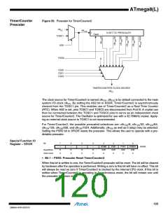
Figure 56. Prescaler for Timer/Counter2
clkI/O
clkT2S
10-BIT T/C PRESCALER
Clear
TOSC1
AS2
PSR2
0
CS20
CS21
CS22
TIMER/COUNTER2 CLOCK SOURCE
clkT2
The clock source for Timer/Counter2 is named clkT2S. clkT2S is by default connected to the main
system I/O clock clkI/O. By setting the AS2 bit in ASSR, Timer/Counter2 is asynchronously
clocked from the TOSC1 pin. This enables use of Timer/Counter2 as a Real Time Counter
(RTC). When AS2 is set, pins TOSC1 and TOSC2 are disconnected from Port B. A crystal can
then be connected between the TOSC1 and TOSC2 pins to serve as an independent clock
source for Timer/Counter2. The Oscillator is optimized for use with a 32.768kHz crystal. Apply-
ing an external clock source to TOSC1 is not recommended.
For Timer/Counter2, the possible prescaled selections are: clkT2S/8, clkT2S/32, clkT2S/64,
clkT2S/128, clkT2S/256, and clkT2S/1024. Additionally, clkT2S as well as 0 (stop) may be selected.
Setting the PSR2 bit in SFIOR resets the prescaler. This allows the user to operate with a pre-
dictable prescaler.
Special Function IO
Register – SFIOR
Bit
7
–
6
–
5
–
4
–
3
ACME
R/W
0
2
1
PSR2
R/W
0
0
PSR10
R/W
0
PUD
R/W
0
SFIOR
Read/Write
Initial Value
R
0
R
0
R
0
R
0
• Bit 1 – PSR2: Prescaler Reset Timer/Counter2
When this bit is written to one, the Timer/Counter2 prescaler will be reset. The bit will be cleared
by hardware after the operation is performed. Writing a zero to this bit will have no effect. This bit
will always be read as zero if Timer/Counter2 is clocked by the internal CPU clock. If this bit is
written when Timer/Counter2 is operating in Asynchronous mode, the bit will remain one until
the prescaler has been reset.
120
2486AA–AVR–02/2013

 ATMEL [ ATMEL ]