ATmega48/88/168
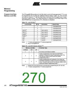
Table 117. Lock Bit Protection Modes(1)(2). Only ATmega88/168.
BLB0 Mode BLB02 BLB01
No restrictions for SPM or LPM accessing the Application
section.
1
2
1
1
1
0
SPM is not allowed to write to the Application section.
SPM is not allowed to write to the Application section, and
LPM executing from the Boot Loader section is not
allowed to read from the Application section. If Interrupt
Vectors are placed in the Boot Loader section, interrupts
are disabled while executing from the Application section.
3
4
0
0
0
1
LPM executing from the Boot Loader section is not
allowed to read from the Application section. If Interrupt
Vectors are placed in the Boot Loader section, interrupts
are disabled while executing from the Application section.
BLB1 Mode BLB12 BLB11
No restrictions for SPM or LPM accessing the Boot Loader
section.
1
2
1
1
1
0
SPM is not allowed to write to the Boot Loader section.
SPM is not allowed to write to the Boot Loader section,
and LPM executing from the Application section is not
allowed to read from the Boot Loader section. If Interrupt
Vectors are placed in the Application section, interrupts
are disabled while executing from the Boot Loader section.
3
4
0
0
0
1
LPM executing from the Application section is not allowed
to read from the Boot Loader section. If Interrupt Vectors
are placed in the Application section, interrupts are
disabled while executing from the Boot Loader section.
Notes: 1. Program the Fuse bits and Boot Lock bits before programming the LB1 and LB2.
2. “1” means unprogrammed, “0” means programmed
271
2545D–AVR–07/04

 ATMEL [ ATMEL ]