ATmega640/1280/1281/2560/2561
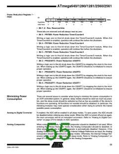
Power Reduction Register 1 -
PRR1
Bit
7
–
6
–
5
PRTIM5
R/W
0
4
PRTIM4
R/W
0
3
PRTIM3
R/W
0
2
PRUSART3
R/W
1
PRUSART2
R/W
0
PRUSART1
R/W
PRR1
Read/Write
Initial Value
R
0
R
0
0
0
0
• Bit 7..6 - Res: Reserved bits
These bits are reserved and will always read as zero.
• Bit 5 - PRTIM5: Power Reduction Timer/Counter5
Writing a logic one to this bit shuts down the Timer/Counter5 module. When the
Timer/Counter5 is enabled, operation will continue like before the shutdown.
• Bit 4 - PRTIM4: Power Reduction Timer/Counter4
Writing a logic one to this bit shuts down the Timer/Counter4 module. When the
Timer/Counter4 is enabled, operation will continue like before the shutdown.
• Bit 3 - PRTIM3: Power Reduction Timer/Counter3
Writing a logic one to this bit shuts down the Timer/Counter3 module. When the
Timer/Counter3 is enabled, operation will continue like before the shutdown.
• Bit 2 - PRUSART3: Power Reduction USART3
Writing a logic one to this bit shuts down the USART3 by stopping the clock to the mod-
ule. When waking up the USART3 again, the USART3 should be re initialized to ensure
proper operation.
• Bit 1 - PRUSART2: Power Reduction USART2
Writing a logic one to this bit shuts down the USART2 by stopping the clock to the mod-
ule. When waking up the USART2 again, the USART2 should be re initialized to ensure
proper operation.
• Bit 0 - PRUSART1: Power Reduction USART1
Writing a logic one to this bit shuts down the USART1 by stopping the clock to the mod-
ule. When waking up the USART1 again, the USART1 should be re initialized to ensure
proper operation.
Minimizing Power
Consumption
There are several issues to consider when trying to minimize the power consumption in
an AVR controlled system. In general, sleep modes should be used as much as possi-
ble, and the sleep mode should be selected so that as few as possible of the device’s
functions are operating. All functions not needed should be disabled. In particular, the
following modules may need special consideration when trying to achieve the lowest
possible power consumption.
Analog to Digital Converter
Analog Comparator
If enabled, the ADC will be enabled in all sleep modes. To save power, the ADC should
be disabled before entering any sleep mode. When the ADC is turned off and on again,
the next conversion will be an extended conversion. Refer to “Analog to Digital Con-
verter” on page 274 for details on ADC operation.
When entering Idle mode, the Analog Comparator should be disabled if not used. When
entering ADC Noise Reduction mode, the Analog Comparator should be disabled. In
other sleep modes, the Analog Comparator is automatically disabled. However, if the
Analog Comparator is set up to use the Internal Voltage Reference as input, the Analog
Comparator should be disabled in all sleep modes. Otherwise, the Internal Voltage Ref-
erence will be enabled, independent of sleep mode. Refer to “Analog Comparator” on
page 271 for details on how to configure the Analog Comparator.
55
2549A–AVR–03/05

 ATMEL [ ATMEL ]