ATmega640/1280/1281/2560/2561
4. Set OE to “0”, and BS1 to “0”. The EEPROM Data byte can now be read at
DATA.
5. Set OE to “1”.
Programming the Fuse Low
Bits
The algorithm for programming the Fuse Low bits is as follows (refer to “Programming
the Flash” on page 341 for details on Command and Data loading):
1. A: Load Command “0100 0000”.
2. C: Load Data Low Byte. Bit n = “0” programs and bit n = “1” erases the Fuse bit.
3. Give WR a negative pulse and wait for RDY/BSY to go high.
Programming the Fuse High
Bits
The algorithm for programming the Fuse High bits is as follows (refer to “Programming
the Flash” on page 341 for details on Command and Data loading):
1. A: Load Command “0100 0000”.
2. C: Load Data Low Byte. Bit n = “0” programs and bit n = “1” erases the Fuse bit.
3. Set BS2, BS1 to “01”. This selects high data byte.
4. Give WR a negative pulse and wait for RDY/BSY to go high.
5. Set BS2, BS1 to “00”. This selects low data byte.
Programming the Extended
Fuse Bits
The algorithm for programming the Extended Fuse bits is as follows (refer to “Program-
ming the Flash” on page 341 for details on Command and Data loading):
1. 1. A: Load Command “0100 0000”.
2. 2. C: Load Data Low Byte. Bit n = “0” programs and bit n = “1” erases the Fuse
bit.
3. 3. Set BS2, BS1 to “10”. This selects extended data byte.
4. 4. Give WR a negative pulse and wait for RDY/BSY to go high.
5. 5. Set BS2, BS1 to “00”. This selects low data byte.
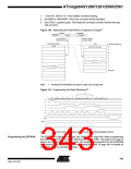
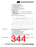
Figure 143. Programming the FUSES Waveforms
Write Fuse Low byte
Write Fuse high byte
Write Extended Fuse byte
A
C
A
C
A
C
0x40
DATA
XX
0x40
DATA
XX
0x40
DATA
XX
DATA
XA1
XA0
BS1
BS2
XTAL1
WR
RDY/BSY
RESET +12V
OE
PAGEL
345
2549A–AVR–03/05

 ATMEL [ ATMEL ]