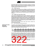
When reading the Extended Fuse byte, load 0x0002 in the Z-pointer. When an (E)LPM
instruction is executed within three cycles after the BLBSET and SPMEN bits are set in
the SPMCSR, the value of the Extended Fuse byte (EFB) will be loaded in the destina-
tion register as shown below. Refer to Table 150 on page 336 for detailed description
and mapping of the Extended Fuse byte.
Bit
Rd
7
6
5
4
3
2
1
0
–
–
–
–
–
EFB2
EFB1
EFB0
Fuse and Lock bits that are programmed, will be read as zero. Fuse and Lock bits that
are unprogrammed, will be read as one.
Reading the Signature Row
from Software
To read the Signature Row from software, load the Z-pointer with the signature byte
address given in Table 137 on page 326 and set the SIGRD and SPMEN bits in
SPMCSR. When an LPM instruction is executed within three CPU cycles after the
SIGRD and SPMEN bits are set in SPMCSR, the signature byte value will be loaded in
the destination register. The SIGRD and SPMEN bits will auto-clear upon completion of
reading the Signature Row Lock bits or if no LPM instruction is executed within three
CPU cycles. When SIGRD and SPMEN are cleared, LPM will work as described in the
Instruction set Manual.
Table 137. Signature Row Addressing
Signature Byte
Z-Pointer Address
0x0000
Device Signature Byte 1
Device Signature Byte 2
Device Signature Byte 3
RC Oscillator Calibration Byte
0x0002
0x0004
0x0001
Note:
All other addresses are reserved for future use.
Preventing Flash Corruption
During periods of low VCC, the Flash program can be corrupted because the supply volt-
age is too low for the CPU and the Flash to operate properly. These issues are the same
as for board level systems using the Flash, and the same design solutions should be
applied.
A Flash program corruption can be caused by two situations when the voltage is too low.
First, a regular write sequence to the Flash requires a minimum voltage to operate cor-
rectly. Secondly, the CPU itself can execute instructions incorrectly, if the supply voltage
for executing instructions is too low.
Flash corruption can easily be avoided by following these design recommendations (one
is sufficient):
1. If there is no need for a Boot Loader update in the system, program the Boot
Loader Lock bits to prevent any Boot Loader software updates.
2. Keep the AVR RESET active (low) during periods of insufficient power supply
voltage. This can be done by enabling the internal Brown-out Detector (BOD) if
the operating voltage matches the detection level. If not, an external low VCC
reset protection circuit can be used. If a reset occurs while a write operation is in
progress, the write operation will be completed provided that the power supply
voltage is sufficient.
3. Keep the AVR core in Power-down sleep mode during periods of low VCC. This
will prevent the CPU from attempting to decode and execute instructions, effec-
326
ATmega640/1280/1281/2560/2561
2549A–AVR–03/05

 ATMEL [ ATMEL ]