– the External Interrupt Request 0. The Interrupt Vectors can be moved to the start of
the Boot Flash section by setting the IVSEL bit in the General Interrupt Control Register
(GICR). Refer to “Interrupts” on page 42 for more information. The Reset Vector can
also be moved to the start of the boot Flash section by programming the BOOTRST
fuse, see “Boot Loader Support – Read-While-Write Self-Programming” on page 241.
When an interrupt occurs, the Global Interrupt Enable I-bit is cleared and all interrupts
are disabled. The user software can write logic one to the I-bit to enable nested inter-
rupts. All enabled interrupts can then interrupt the current interrupt routine. The I-bit is
automatically set when a Return from Interrupt instruction – RETI – is executed.
There are basically two types of interrupts. The first type is triggered by an event that
sets the interrupt flag. For these interrupts, the Program Counter is vectored to the
actual Interrupt Vector in order to execute the interrupt handling routine, and hardware
clears the corresponding interrupt flag. Interrupt flags can also be cleared by writing a
logic one to the flag bit position(s) to be cleared. If an interrupt condition occurs while the
corresponding interrupt enable bit is cleared, the interrupt flag will be set and remem-
bered until the interrupt is enabled, or the flag is cleared by software. Similarly, if one or
more interrupt conditions occur while the Global Interrupt Enable bit is cleared, the cor-
responding interrupt flag(s) will be set and remembered until the global interrupt enable
bit is set, and will then be executed by order of priority.
The second type of interrupts will trigger as long as the interrupt condition is present.
These interrupts do not necessarily have interrupt flags. If the interrupt condition disap-
pears before the interrupt is enabled, the interrupt will not be triggered.
When the AVR exits from an interrupt, it will always return to the main program and exe-
cute one more instruction before any pending interrupt is served.
Note that the Status Register is not automatically stored when entering an interrupt rou-
tine, nor restored when returning from an interrupt routine. This must be handled by
software.
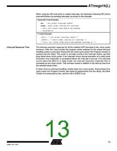
When using the CLI instruction to disable interrupts, the interrupts will be immediately
disabled. No interrupt will be executed after the CLI instruction, even if it occurs simulta-
neously with the CLI instruction. The following example shows how this can be used to
avoid interrupts during the timed EEPROM write sequence.
Assembly Code Example
in r16, SREG
; store SREG value
cli ; disable interrupts during timed sequence
sbi EECR, EEMWE
sbi EECR, EEWE
out SREG, r16
; start EEPROM write
; restore SREG value (I-bit)
C Code Example
char cSREG;
cSREG = SREG; /* store SREG value */
/* disable interrupts during timed sequence */
_CLI();
EECR |= (1<<EEMWE); /* start EEPROM write */
EECR |= (1<<EEWE);
SREG = cSREG; /* restore SREG value (I-bit) */
12
ATmega16(L)
2466E–AVR–10/02

 ATMEL [ ATMEL ]